


EN 47
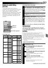
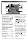
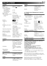
Controls
1 MONITOR OPEN Switch.................... ੬ pg. 16
2 REW Button ....................................... ੬ pg. 34
RETAKE R [Quick Review] Button .......
੬ pg. 19
3 FF Button ........................................... ੬ pg. 34
RETAKE F Button................................
੬ pg. 19
4 PLAY/PAUSE Button........................... ੬ pg. 34
5 STOP Button ...................................... ੬ pg. 34
6 SEL. Button ........................................ ੬ pg. 25
7 SET Button ......................................... ੬ pg. 25
8 Power Zoom Lever ............................ ੬ pg. 18
9 DISPLAY Button ................................. ੬ pg. 15
0 MENU Button .................................... ੬ pg. 30
! Multi-Function Control
•Exposure +/– ...................................
੬ pg. 24
•Focus FAR/NEAR ............................. ੬ pg. 22
•Menu Setting Change .......................
੬ pg. 30
•Tracking +/– ....................................
੬ pg. 35
@ PUSH Button ..................................... ੬ pg. 13
# EJECT Switch...................................... ੬ pg. 13
$ BATT. [Battery] RELEASE Switch ......... ੬ pg. 8
% Diopter Adjustment............................ ੬ pg. 10
^ Recording Start/Stop Button ................ ੬ pg. 15
& POWER Switch ..............................੬ pg.15, 34
* Recording Mode [SP/EP] Select
Button ................................................ ੬ pg. 12
R.A.EDIT CANCEL Button ...................
੬ pg. 40
( R.A.EDIT IN/OUT Button.................... ੬ pg. 40
) Tape Length [T20•30•40]
Select Button...................................... ੬ pg. 12
COUNTER R [Reset]/M [Memory]
Button ................................................
੬ pg. 35
q EDIT Button ....................................... ੬ pg. 41
w R.A.EDIT Button................................. ੬ pg. 40
e PICTURE STABILIZER Button ..............੬ pg. 24
r PROGRAM AE Select Dial ..................੬ pg. 20
t BRIGHT Dial ..................................... ੬ pg. 34
y VOLUME Dial ................................... ੬ pg. 34
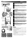
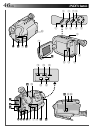
Connectors
u J terminal (JLIP (Joint Level Interface Protocol)
Connector.)
(Located beneath the jack cover)
• Connect the Editing Cable when performing
Random Assemble Editing (
੬ pg. 40).
•It is used to connect the camcorder to a device
such as a personal computer.
For further detail consult your nearest JVC
dealer.
i DC IN Jack ......................................... ੬ pg. 9
The jacks
o to Q are located beneath the jack
cover.
o VIDEO OUT Jack ............................... ੬ pg. 36
p RF DC OUT Jack ................................ ੬ pg. 36
Q AUDIO OUT Jack .............................. ੬ pg. 36
Indicators
W Tally Lamp ......................................... ੬ pg. 15
E Power On Indicator ........................... ੬ pg. 15
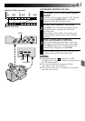
Other Parts
R Camera sensor
Be careful not to cover this area; built-in
here is the sensor necessary for shooting.
T Microphone
Y Shoulder Strap Eyelets ........................ ੬ pg. 14
U Clock Battery Compartment ................੬ pg. 10
I Battery Pack Mount ........................... ੬ pg. 8
O Electronic Viewfinder......................... ੬ pg. 10
P LENS COVER Switch ......................... ੬ pg. 15
a Grip Strap .......................................... ੬ pg. 14
s Speaker .............................................. ੬ pg. 34
d Tripod Mounting Socket ......................੬ pg. 14