


EN 9
GETTING STARTED
MasterPage: Start_Right
GETTING STARTED
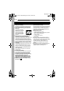
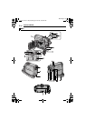
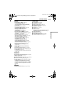
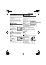
Controls
A Rewind Button [
3
] (੬ pg. 21)
Left Button [ ] (੬ pg. 15)
Quick Review Button [QUICK REVIEW]
(੬ pg. 20)
B Set Button [SET] (੬ pg. 15)
Data Battery Button [DATA] (੬ pg. 13)
C Stop Button [8] (੬ pg. 21)
Backlight Compensation Button
[BACKLIGHT] (੬ pg. 29)
Down Button [ ] (੬ pg. 15)
D Play/Pause Button [4/9] (੬ pg. 21)
Manual Focus Button [FOCUS] (੬ pg. 28)
Up Button [ ] (੬ pg. 15)
E Wide 16:9 Button [16:9] (੬ pg. 27)
Blank Search Button [BLANK] (੬ pg. 21)
F Menu Button [MENU] (੬ pg. 23)
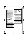
G Fast-Forward Button [
5
] (੬ pg. 21)
Right Button [ ] (੬ pg. 15)
Night Button [NIGHT] (੬ pg. 27)
H Dioptre Adjustment Control (੬ pg. 16)
I Auto Button [AUTO] (੬ pg. 14)
J Snapshot Button [SNAPSHOT] (੬ pg. 27)
K Power Zoom Lever [T/W] (੬ pg. 19)
Speaker Volume Control [VOL. +, –]
(੬ pg. 21)
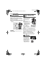
L Battery Release Button [PUSH BATT.]
(੬ pg. 12)
M Recording Start/Stop Button (੬ pg. 18)
N Power Switch [REC, OFF, PLAY] (੬ pg. 14)
O Lock Button (੬ pg. 14)
P Cassette Open/Eject Switch [OPEN/EJECT]
(੬ pg. 17)
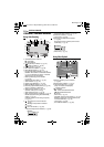
Connectors
The connectors are located beneath the covers.
Q Audio/Video Output Connector
[AV] (੬ pg. 22, 33)
R S-Video Output Connector [S] (੬ pg. 22, 33)
S DC Input Connector [DC] (੬ pg. 12)
T Digital Video Connector [DV OUT] (i.LINK*)
(੬ pg. 34, 35)
* i.LINK refers to the IEEE1394-1995 industry
specification and extensions thereof. The logo
is used for products compliant with the i.LINK
standard.
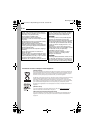
Indicators
U POWER/CHARGE Lamp (੬ pg. 12, 18)
Other Parts
V LCD Monitor (੬ pg. 18)
W Viewfinder (੬ pg. 16)
X Battery Pack Mount (੬ pg. 13)
Y Shoulder Strap Eyelet (੬ pg. 12)
Z Speaker (੬ pg. 21)
a Grip Strap (੬ pg. 15)
b Lens
c Camera Sensor
(Be careful not to cover this area, a sensor
necessary for shooting is built-in here.)
d Stereo Microphone
e Stud Hole (੬ pg. 16)
f Tripod Mounting Socket (੬ pg. 16)
g Cassette Holder Cover (੬ pg. 17)
G R-D 3 4 0 P A L.b o o k P ag e 9 Thursday , October 27 , 2005 3:19 PM