


EN61
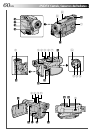
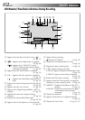
Controls
1 Monitor Open Button
[PUSH OPEN] ..................................... ੬ pg. 16
2 Dioptre Adjustment Control ................. ੬ pg. 10
3 Battery Release Switch
[BAT. RELEASE]...................................... ੬ pg. 8
4 •MENU Wheel [+, –, PUSH] ............... ੬ pg. 34
•LCD Monitor BRIGHT
(Brightness) Control [+, –] .................. ੬ pg. 16
5 Snapshot Button [SNAPSHOT] ............. ੬ pg. 30
6 •Power Zoom Lever [T/W] .................. ੬ pg. 18
•Speaker Volume Control [VOL.] ........ ੬ pg. 20
7 •FOCUS Button .................................. ੬ pg. 25
•BLANK SEARCH Button .................... ੬ pg. 21
8 •Stop Button [5]................................. ੬ pg. 20
•NIGHT-SCOPE Button....................... ੬ pg. 26
9 •Rewind Button [
2
] ......................... ੬ pg. 20
•EXPOSURE Button ............................ ੬ pg. 32
0 •Play/Pause Button [
4
/6] ................... ੬ pg. 20
•Programme AE Button [P.AE] ............. ੬ pg. 26
! •Fast-Forward Button [
3
] ................. ੬ pg. 20
•BACKLIGHT Button .......................... ੬ pg. 32
@ Power Switch [ , , , OFF] ...... ੬ pg. 17
# Recording Start/Stop Button.................. ੬ pg. 16
$ Lock Button ......................................... ੬ pg. 17
% OPEN/EJECT Switch ............................. ੬ pg. 13
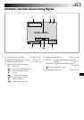
Connectors
The connectors ^ to ( are located beneath a cover.
^ S-Video Output Connector
[S] ........................................... ੬ pg. 22, 40, 46
& PC (DIGITAL PHOTO) Connector ........ ੬ pg. 51
* J Terminal [JLIP
(Joint Level Interface Protocol)]............. ੬ pg. 46
Connect to a JLIP-compatible camcorder or VCR
to control it from the computer using the
Software.
Connect the editing cable when performing
Random Assemble Editing............ ੬ pg. 45 – 49
( Audio/Video Output Connector
[AV] ........................................ ੬ pg. 22, 40, 46
) DC Input Connector .......................... ੬ pg. 8, 9
q Digital Video Connector
[DV OUT] (i.Link*) .................. ੬ pg. 41, 51, 52
* i.Link refers to the IEEE1394-1995 industry
specification and extensions thereof. The logo
is used for products compliant with the i.Link
standard.
Indicators
w Tally Lamp..................................... ੬ pg. 16, 36
e CHARGE Lamp...................................... ੬ pg. 8
r Power Lamp .................................. ੬ pg. 16, 17
Other Parts
t •Remote Sensor .................................. ੬ pg. 42
•Camera Sensor
Be careful not to cover this area, a sensor
necessary for shooting is built-in here.
y Viewfinder ........................................... ੬ pg. 10
u Stereo Microphone .............................. ੬ pg. 50
i Shoulder Strap Eyelets.......................... ੬ pg. 11
o Grip Strap............................................ ੬ pg. 10
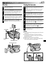
p Viewfinder Cleaning Hatch .................. ੬ pg. 65
Q Battery Pack Mount ............................... ੬ pg. 8
W LCD Monitor ................................. ੬ pg. 16, 17
E Speaker ............................................... ੬ pg. 20
R Stud Hole ............................................ ੬ pg. 11
T Tripod Mounting Socket ....................... ੬ pg. 11