


76 EN
CONTROLS, INDICATIONS AND CONNECTORS
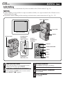
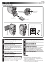
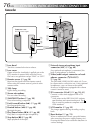
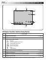
1 Lens hood
Turn this counterclockwise to release.
2 Lens cover
Opens when the viewfinder is pulled out or the
LCD monitor is opened fully with the Power
Dial set to any position except “PLAY” or “OFF”.
3 Remote sensor (੬ pg. 50)
Receives the signal from the remote control.
When using the remote control, point it at the
remote sensor.
4 Tally lamp
Lights during recording.
5 Stereo microphone
For use when recording.
6 SNAPSHOT button (੬ pg. 28)
Press when taking a snapshot.
7 Fast-Forward button (
3
) (੬ pg. 48)
Fast-Forwards the tape.
8 Rewind button (
2
) (੬ pg. 48)
Rewinds the tape.
9 Play/Pause button (6/
4
) (੬ pg. 48)
Plays back or stops the tape temporarily.
0 Stop button (5) (੬ pg. 48)
Stops playback of the tape.
2
1
3
4
6
7
8
9
0
!
@
#
5
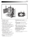
Connector cover
Pull this out to open.
Camcorder
! External stereo microphone input
connector (MIC) (
੬ pg. 68)
If an optional microphone is connected, the
built-in microphone is disabled.
@ Video/audio output connector or head-
phones connector (
/AV-OUT)
(
੬ pg. 54)
The provided VIDEO/AUDIO cable (ø3.5) can
be connected to a television etc. Using optional
headphones, you can listen to the sound.
However, headphones equipped with volume
control cannot be used.
# DV connector (i.Link*) (੬ pg. 58, 61)
Connect a video unit equipped with a DV
connector.
*i.Link refers to the IEEE1394-1995 industry
specification and extensions thereof. The
logo is used for products compliant with the
i.Link standard.
$ LCD monitor (੬ pg. 22)
The image appears during recording or play-
back.
% Reset button (੬ pg. 74)
When a malfunction occurs, press this button
after removing the power supply (battery etc.).
Pressing this button also resets the date/time or
various settings.