


EN
81
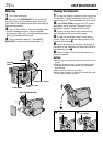
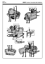
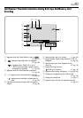
Controls
1 OPEN/EJECT Switch ............................ ੬ pg. 12
2 •Stop Button [5].................................... ੬ pg. 21
•BACKLIGHT Button ............................. ੬ pg. 42
3 •Rewind Button [
2
]............................. ੬ pg. 21
•NIGHT Button ...................................... ੬ pg. 36
4 Play/Pause Button [
4
/6] ....................... ੬ pg. 21
5 Fast-Forward Button [
3
] ..................... ੬ pg. 21
6 Monitor Open Button [PUSH OPEN] ..... ੬ pg. 16
7 Diopter Adjustment Control.................... ੬ pg. 10
8 Battery Release Button
[BATT. RELEASE] ................................... ੬ pg. 8
9 Recording Start/Stop Button.................. ੬ pg. 16
0 •MENU Wheel [+, –, PUSH].................. ੬ pg. 44
•LCD Monitor BRIGHT (Brightness)
Control [+, –] ........................................ ੬ pg. 16
! Snapshot Button
[SNAPSHOT]....................... ੬ pg. 26, 27, 40, 52
@ •Power Zoom Lever [T/W]..................... ੬ pg. 18
•Speaker Volume Control [VOL.] .......... ੬ pg. 21
# •FOCUS Button..................................... ੬ pg. 41
•BLANK Button ..................................... ੬ pg. 24
$ Lock Button............................................ ੬ pg. 17
% Power Switch
[
AUTO
,
MANUAL
, PLAY, OFF] ................. ੬ pg. 17
^ INDEX Button
(GR-DVL720/DVL520 only) ................... ੬ pg. 29
& INFO Button
(GR-DVL720/DVL520 only) ................... ੬ pg. 29
* VIDEO/MEMORY Switch [VIDEO, MEMORY]
(GR-DVL720/DVL520 only) ................... ੬ pg. 17
( Video Light Switch
[LIGHT OFF/AUTO/ON]......................... ੬ pg. 19
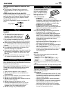
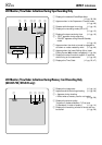
Connectors
The connectors ) to w are located beneath a cover.
) Audio/Video Output Connector
[AV] ............................................ ੬ pg. 22, 50, 59
q •J Terminal [JLIP (Joint Level Interface Protocol)]
(GR-DVL320 only) ............................... ੬ pg. 59
You can also connect to a JLIP-compatible
camcorder or VCR to control it from the
computer using the optional Software HS-V16U.
•Edit Connector [EDIT]
(GR-DVL720/DVL520 only) ................. ੬ pg. 59
w DC Input Connector ............................. ੬ pg. 8, 9
e Digital Video Connector
[DV IN/OUT] (i.Link*) ....................... ੬ pg. 51, 65
*i.Link refers to the IEEE1394-1995 industry
specification and extensions thereof. The logo
is used for products compliant with the i.Link
standard.
r S-Video Output Connector
[S-VIDEO].................................. ੬ pg. 22, 50, 59
t • PC Connector (GR-DVL320 only) ....... ੬ pg. 65
• USB (Universal Serial Bus) Connector
(GR-DVL720/DVL520 only) ................. ੬ pg. 65
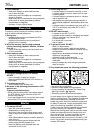
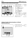
Indicators
y Tally Lamp ....................................... ੬ pg. 16, 46
u CHARGE Lamp ....................................... ੬ pg. 8
i Power Lamp .................................... ੬ pg. 16, 17
Other Parts
o • Remote Sensor.................................... ੬ pg. 53
• Camera Sensor
Be careful not to cover this area, a sensor
necessary for shooting is built-in here.
p Viewfinder .............................................. ੬ pg. 10
Q Video Light............................................. ੬ pg. 19
W Stereo Microphone ................................ ੬ pg. 63
E Viewfinder Cleaning Hatch .................... ੬ pg. 74
R Shoulder Strap Eyelets .......................... ੬ pg. 10
T Grip Strap .............................................. ੬ pg. 10
Y LCD Monitor .................................... ੬ pg. 16, 17
U Speaker ................................................. ੬ pg. 21
I Battery Pack Mount ................................. ੬ pg. 8
O Stud Hole ............................................... ੬ pg. 10
P Tripod Mounting Socket......................... ੬ pg. 10
a MEMORY CARD Cover
(GR-DVL720/DVL520 only) ................... ੬ pg. 14