


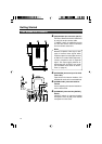
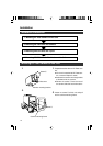


18
CALLTALLY
INTERCOM
LEVEL
FULL AUTOF1
SHUTTER
GAIN
F2
F3
MENU/SHUTTER GAIN
PAINT AUTO
BR
W.BAL
AUTO
MANU
WHITE MASTER BLACK
POWER
I
O
IRIS
STEP
SHUTTER
MENU
PUSH-ON
DOWNUP
VARIABLE
PUSH-ON
HIGH
LOW
B
A
PRESET
CLOSE OPEN
MID
DOWNUP
F4
BARS
REMOTE CONTROL UNIT RM-P210
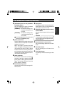
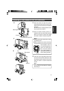
BREAKER
F.f
ft
m
30
1035
15
10
7
2
1.5
5
4
1.2
5.5 10
C16
11
8
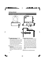
MACRO
PROMPTER
OUTPUT
RM
MENU
AW
BARS
SET
LENS
REMOTE
GENLOCK IN
VIDEO OUT
DC IN
POWER
SEE INST
INTERCOM
INCOM MIC
INCOM LEVEL
ON
OFF
MAXMIN
DYNAMIC
CARBON
PUSH
CALL
VF
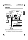
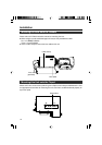
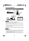
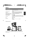
Connecting to Remote Control Unit RM-P210
Headset
KA-310U
Headset
KA-310U
26 Pin
camera
cable
RM Multi-pin
connector
[INTERCOM] terminal
Remote control unit RM-P210
Monitor
[PROMPTER OUTPUT] terminal
Connection
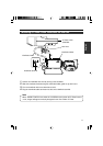
Switch off RM-P210 power supply before attempting the connection.
● Connect this unit’s RM multi-pin connector and RM-P210 using the 26 Pin camera cable.
Length of the camera cable should not be longer than 100 m.
● If intercom headset is to be used, plug the Headset KA-310U into the [INTERCOM] termi-
nal.
● Prompter video (RM-P210 [AUX VIDEO INPUT] terminal’s input signal) from RM-P210
could be verified by connecting this unit’s [PROMPTER OUTPUT] terminal located in front
of it to a monitor using BNC cable.
26 Pin camera cable
VC-P110 (5 m)
VC-P112 (20 m)
VC-P113 (50 m)
VC-P114 (100 m)
Note
Power for this unit and the camera is supplied by RM-P210 via the 26 Pin camera cable.
Setting
Ⅵ Menu screen setting
● Composite video signal is always output at the RM multi-pin connector.In addition, another
type of video signal which could be either RGB component, Y/Cb/Cr component or YC
separate signal could be outputted. The output signal could be selected using the “OUT-
PUT” item under the “SYSTEM” menu screen.
● If the output signal is RGB component, option to superimpose SYNC signal onto the G
signal could be selected through the “SYNC ON G” item under the “SYSTEM” menu screen.
Connecting RM-P210