is a Registered Trademark owned by Victor Company of Japan, Limited.
is a Registered Trademark in Japan, the U.S.A., the U.K. and many other countries.
®
®
®
Printed in Thailand
LWT0260-001A-H
CAUTION
3
4
5
5.
1.
3.
6
1.
2.
2
CAUTION
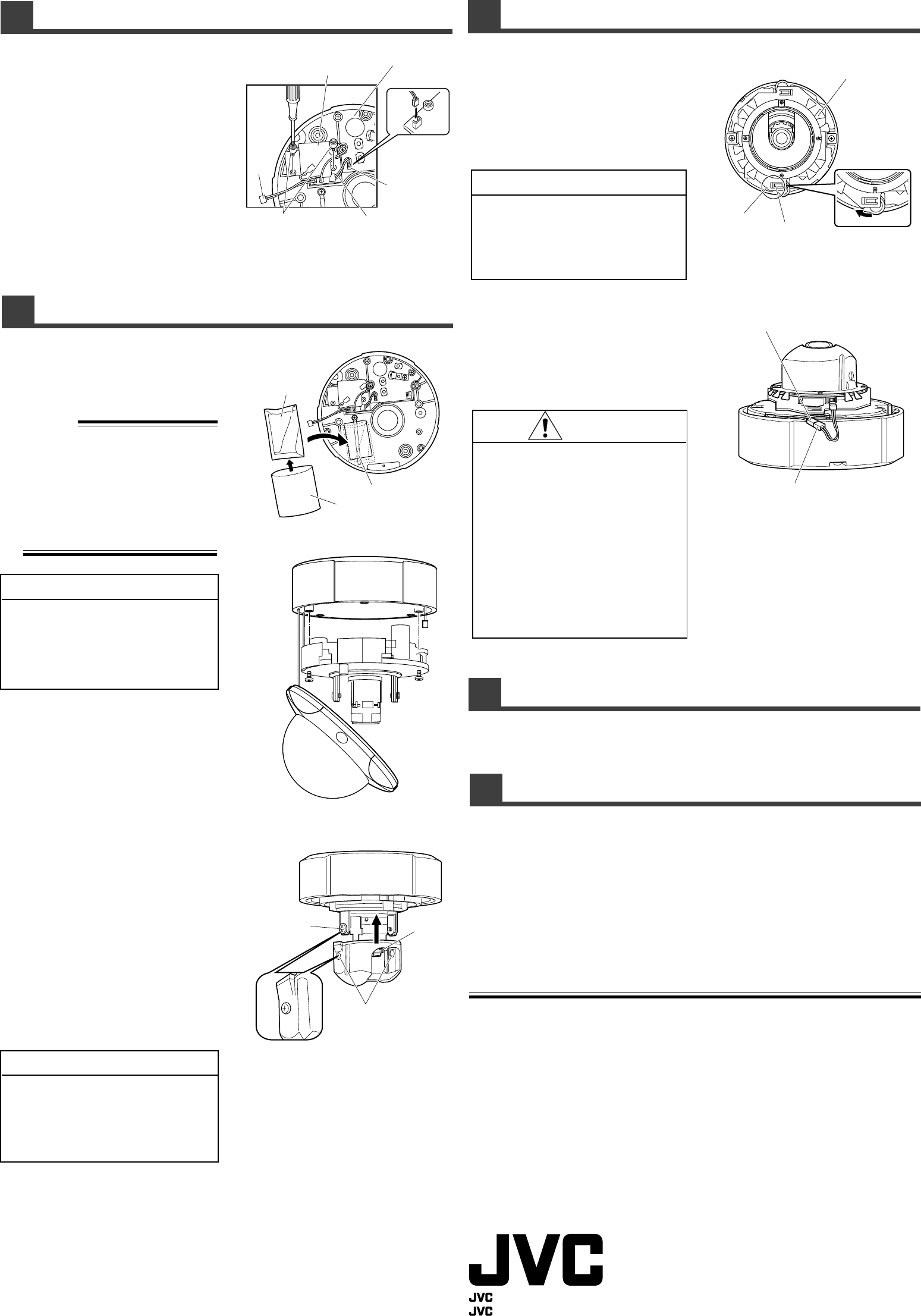
Installing the control board
1.
Install the control board
Use the supplied two screw assy on the
left side of the terminal board and install
the control board.
2.
Connect the CN4 cable
Connect the CN4 cable on the control
board to the CN4 terminal on the terminal
board.
Meanwhile, bring the CN5 cable out of the
base.
Terminal board
Control boardn
CN5
Cable
CN4 terminal
CN4 cable
Screw assy
(attached)
Before installing the heater board
1.
Put the desiccant inside
the base
Put the desiccant that comes with this unit
inside the base and secure with a lug plate.
Memo:
• Remove the desiccant from its silver
packaging before use.
• Always replace the desiccant during
repair, reconnection during maintenance
or reinstallation.
When replacing the desiccant, use a
desiccant with Service Parts No.
LW40790-001A.
Silver packaging
Desiccant
Lug plate
2
1
Tilt lock screw
C section
Notch
Always use the desiccant that comes with
this unit. Other desiccants or the silica gel
that comes with TKC205VPU (A) are unable
to remove moisture completely under
extreme low temperature.
3.
Install the camera unit
Align
1
and
2
of the base with
1
and
2
of the camera unit and tighten with screws.
When doing this, tighten the screws of the
camera unit in the order of
1
,
2
.
4.
Adjust the field angle and
lens of the camera
Switch on the power supply of the camera.
Refer to TK-C205VPU (A) “INSTRUC-
TIONS” on how to adjust the field angle
and lens of the camera.
After adjusting the field angle and lens of
the camera, switch off the power supply
of the camera.
CAUTION
When the heater board is installed, the
switch on the camera unit is hidden and
image adjustment cannot be made. Always
adjust the image quality before installing the
heater.
5.
Install the inner cover
Mount the inner cover such that the tilt lock
screw can be seen from the hole on C
section. When mounting, make sure that
the notch of the inner cover comes to the
direction which the lens of the camera is
facing.
Installing the heater board
1.
Install the heater board to
the camera unit
Rotate the heater in the direction of the
arrow such that the claw (B section) of the
heater board is hooked on the notch (A
section) of the camera unit.
• When connecting CN5 cable of the control
board to the CN5 cable of the heater
board under cold weather conditions
below 50˚F (10˚C), the heater will turn ON
automatically and become very hot. Avoid
being scalded.
• Heater elements could be hot! When
camera power is on, use with caution
when adjusting the camera.
• Make sure that the cable does not touch
the components such as resistors on the
heater board.
Installing the dome cover
Refer to TK-C205VPU (A) “INSTRUCTIONS” for the installation method of the dome cover.
Check items after installation
Check the following items after installation.
□
Is the power supply for TK-C205VPU (A) AC 24 V?
□
Have you inserted the desiccant that comes with this unit?
□
Are the CN5 cables inserted between the base and camera unit?
□
Does the cable touch the components such as resistors on the heater board?
□
Does an image appear normally on the monitor after switching on the power for TK-C205VPU (A)?
Specifications
Power supply / Voltage
:AC 24 V ± 10%, 60 Hz/50 Hz (recommended)
Power consumption : 15 W (during AC 24 V)
Heater operation : Surrounding temperature -40˚F to 32˚F (-40˚C to 0˚C) (auto on/off)
*By using this unit, the operation guarantee temperature of the camera
becomes -40˚F to 122˚F (-40˚C to 50˚C).
Locations free from vibration and shock
Locations free from salt erosion and corrosive gases
Mass :
100˝ (total mass of heater board, control board, desiccant and screw assy)
Accessories : • Instructions ............. 1 • Warranty Card ............... 1
• Service Information • Desiccant (Service Parts
Card........................ 1 No. LW40790-001A)...... 1
• Heater unit .............. 1 • Screw assy.................... 2
A section
B section
Heater board
CN5 cable of heater board
CN5 cable of control board
Install the heater after adjusting the field angle and lens of the camera.
2.
Install TK-C205VPU (A) on
the ceiling
Refer to TK-C205VPU (A) “INSTRUC-
TIONS” for the installation method.
CAUTION
• Pay attention when installing the heater
board to the camera unit as there is a
correct direction.
• The dome cover cannot be installed if the
heater board is not installed securely.
2.
Connect the cable
Connect the CN5 cable of the control
board to the CN5 cable of the heater
board.
Once the CN5 cables are connected,
insert them between the base and camera
unit.
* Design and specifications are subject to change without notice.
© 2005 Victor Company of Japan, Limited
KA-H205U_LWT0260-001A-H 05.2.17, 9:22 AM2


