


Connection and Installation Instructions
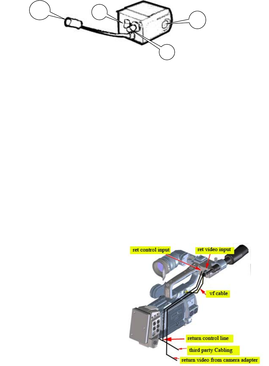
1. GY-HD250U EVF Input (20-Pin Male)
This connection is used to provide the EVF output signal from the GY-HD250 to the
return video unit. Connect this plug to the GY-HD250U’s 20-Pin RGB viewfinder output.
2. Return Control Input (Wire)
This input is used to switch the unit’s output between the GY-HD250U’s VF video and
the return video. Connect his input to GY-HD250U’s 10-pin studio connector with the
wire supplied by either Camplex or Telecast Fiber camera adapter cabling (See
previous page for the respective third-party CCU cabling part numbers).
3. Return Video Input (BNC Male)
Connect the third-party camera adapter VBS return video signal to this BNC input.
4. EVF Output Connection (20-Pin Female)
Insert the GY-HD250U’s 20-pin EVF connector to this output.
Required Camera Settings
! Set the GY-HD250 menu selection “VF SIGNAL” to “RGB”.
! Set the GY-HD250 menu selection “Tally System” to “Studio”.
The EVF signal switching is controlled by the KA-R25U return video unit. The normal EVF
output is the GY-HD250U RGB signal. When the RET (return) button located on the lens
control handle is depressed and held down, a converted Black & White image of the return
video signal is shown in the EVF. Once the RET button is released, the KA-R25U switches
the EVF image back to the RGB signal from the camcorder.
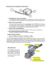
Mounted View
The KA-R25U return video
unit mounts conveniently on
the GY-HD250U’s handle as
shown (right). The original
EVF and microphone can be
used after the return video
unit is mounted.
1
2
3
4