


26
Installation and Connection
Use the piping hole to mount the camera.
Mounting the camera using the piping
hole at the bottom surface of the base
1.Setting the switches (A Pg. 17)
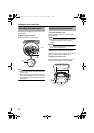
2.Removing the camera unit from the base.
(A Pg. 17 , step 1)
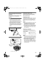
3.Mount the fall prevention wire to the base
(A Pg. 18)
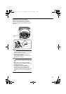
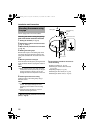
4.Binding the sealing tape
Bind at least 2 layers of the sealing tape to the
joint of the pipe (point where the thread of the
piping hole coincides with the screw hole of the
pipe).
5.Mounting the base to the pipe
Screw the base into the pipe by turning the base
in the clockwise direction. (Piping hole: G3/4-14
UNC)
Note:
● When screwing in the pipe, make sure that
not more than 12 mm (15/32 inch) of the pipe
is being screwed in. Failure to do so may
damage the internal components of this unit.
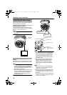
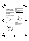
6.Fastening the base to the ceiling
Fasten the base to the ceiling firmly using 2
RM4 mm screws.
Note:
● R4 mm screws are not supplied with this
product. Use appropriate type of screw
according to the material of the mounting
place.
● Check to ensure that there is no space
between the ceiling and base.
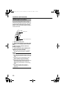
7.Mounting the fall prevention wire to a firm
place (A Pg. 18)
8.The following procedures are same as
normal mounting
●Cable Connection (A Pg. 19)
●Mounting the camera unit to the base
(A Pg. 20)
●Adjusting Images (A Pg. 22)
●Mounting the inner dome (A Pg. 24)
●Mounting the dome cover (A Pg. 24)
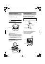
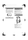
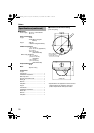
Mounting the camera using
the pipe
4
5
6
7
3
Fall Prevention Wire
Sealing Tape
12 mm(15/32 inch)
and below
R4 mm screw
TK-C215VP4_JP.book Page 26 Wednesday, September 20, 2006 5:48 PM