


2
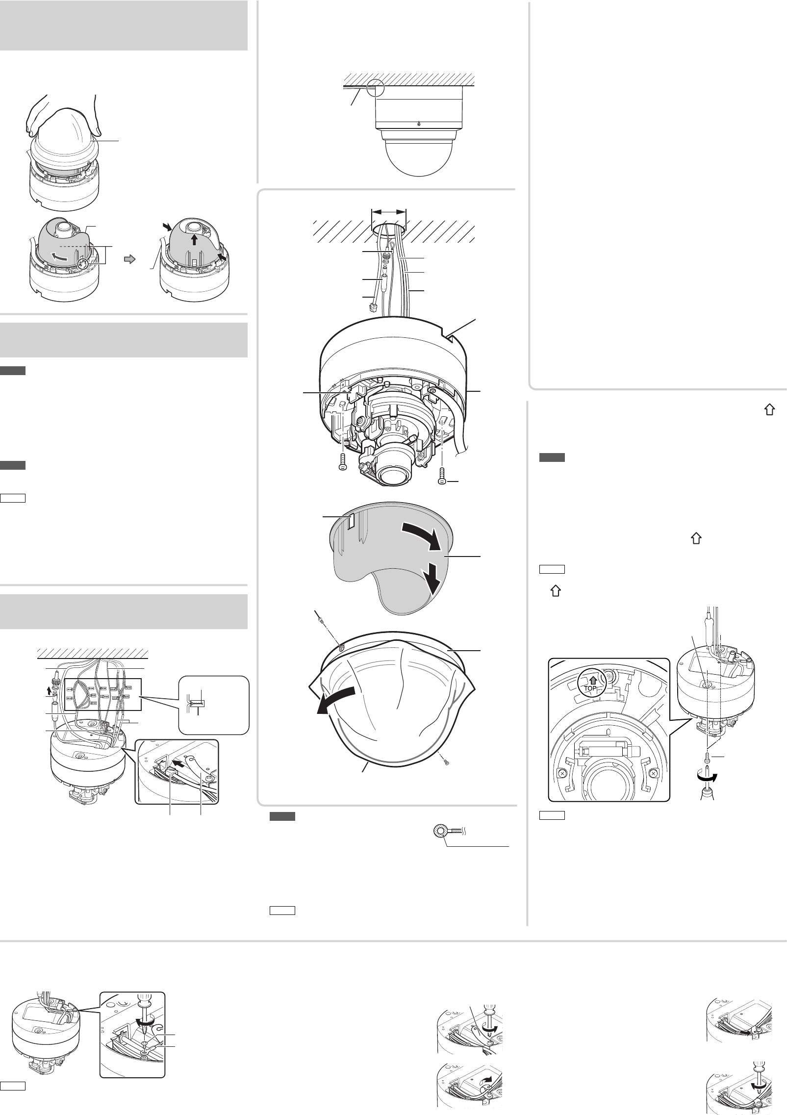
Mounting the Camera
When mounting the camera with
cables pulled out from the side
If you cannot cut a large enough hole in the ceiling or
walls, connect by pulling the cables out through the
opening in the side of the camera body.
Power cable (VN-H257U)
Alarm cable (VN-H257U)
Audio cable (VN-H257U)
LAN cable
Monitor output cable
☞ Continue to next page
Removing the dome cover
and inner dome
• Turn the dome cover counterclockwise to remove it.
• Turn the inner dome 45 degrees counterclockwise and grasp the
inner dome near the stops (two locations) to remove it.
1
2
Dome cover
Inner dome
Knob (two
locations)
Fall prevention
sheet
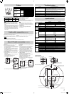
Align the mounting direction mark ( )
with the shooting direction, and mount
the camera body on the ceiling or wall
Note
• Mounting hole is
Φ
4.5 mm.
• Do not use a flat head screw.
• If you use an impact driver, tighten by hand. Otherwise, the case
may be damaged.
• Use the appropriate screws and tighten securely.
• Use a screw with a head between
Φ
6.5 mm and
Φ
11 mm.
Align the mounting direction mark ( ) with the shooting
direction, and mount the camera.
Memo
• When you mount it on the wall, make the mounting direction mark
( ) face up.
Mounting hole (
Φ
4.5 mm)
Attachment screw
(Prepared by
customer)
Memo
• Secure the dome cover using two dome cover setscrews as
required.
Note
Read before starting work.
• Special skills are required to install this unit.
• Install this unit on a location that is strong enough to hold it.
•
Make sure you turn off the power supply to the device before starting work.
• When you attach the camera body to the ceiling, be sure to wear
safety goggles to protect your eyes from falling objects.
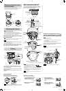
Opening a hole (approx. Φ 30 mm) on
the ceiling or wall
Note
• Take note of the length, strength and pull of the fall prevention wire.
For the fall prevention wire use the insulation material.
Memo
• When you directly mount the camera on the ceiling, use the ceiling
mount bracket (WB-S2205).
• To mount the camera using an electrical box, consult your dealer or
a JVC Service Center near you.
Open a hole in the ceiling or wall (approx. Φ 30 mm), and
pull out the fall prevention wire and cables from the hole (the
fall prevention wire and cables are not provided).
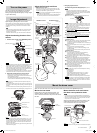
3 Fasten the free end of
the wire clamp with the
attachment screw of the wire
clamp.
4 Tighten the attachment
screw of the wire clamp and
fix the LAN cable.
Securing the LAN cable
Secure the LAN cable using the wire clamp.
1 Loosen the attachment screw
of the wire clamp until it is
loose but not disconnected.
Wire clamp
2 Roll the wire clamp around
the LAN cable.
Attachment screw of
the wire clamp
Securing cables
Securing the fall prevention wire
Secure the fall prevention wire using the wire setscrew.
Fall prevention wire
setscrew
Fall prevention wire
Memo
• Take note of the length and strength of the fall prevention wire. Use wire
made of insulated material. Make the wire length as short as possible.
Note
• The inner diameter of the ring section of
the fall prevention wire should be between
Φ
3.1 mm and
Φ
5.5 mm.
Φ
3.1 to
Φ
5.5 mm
• Securely lock the LAN cable so that it will not be disconnected.
• Be sure to properly ground the PoE power sourcing equipment
before use.
• If you use both the AC 24 V power cable and the PoE-based LAN
cable simultaneously, the camera may fail. Always supply power
using either method.
Memo
• Put the cables into the hole that you opened on the ceiling or wall
after connecting.
Cabling
LAN cable
LAN cable
Monitor output
cable
Alarm cable
(VN-H257U)
Power cable
(VN-H257U)
Fall prevention wire
Soldering or crimping
Wrapping insulation
tapes
Audio cable
(VN-H257U)
Wire clamp
Connect the AC 24 V power cable, alarm cable, and
audio cable to their respective connectors by crimping
them or soldering them.
Wrap unused connectors and the ends of unused cables
with insulation tape.
Make sure the LAN cable is completely inserted into the
connector.
Camera
body
Inner
dome
Dome
cover
Approx.
Φ
30 mm
Fall prevention wire
(Prepared by customer)
Monitor output cable
LAN cable
Knob
(two
locations)
Fastening
screw
Dome cover protective sheet
Dome cover
setscrews
Inner
depression
Side opening for cables
Alarm cable (VN-H257U)
Power cable (VN-H257U)
Audio cable (VN-H257U)
(The VN-H257U camera is shown in the illustration.)
EN_VN-H237_001D_Non-Mask.indb 2EN_VN-H237_001D_Non-Mask.indb 2 5/24/2012 2:24:07 PM5/24/2012 2:24:07 PM