


8 9
⿎
Main specications of Chroma Meter CL-200A
Model Chroma Meter CL-200A
Luminance meter
class
Conforms to requirements for Class AA of JIS C 1609-1: 2006 "Illuminance
meters Part 1: General measuring instruments"
Relative spectral
response
Closely matches CIE Standard Observer curves x¯ (
λ
), y¯(
λ
), and z¯(
λ
)
Within 6% (f
i
') of the CIE spectral luminous efcency V(
λ
)
Cosine response
(f
2
) E
v
: Within 3%
Receptor Silicon photocell
Measuring
function
Tristimulus values: XYZ
Chromaticity: E
v
xy; E
v
u'v'; E
v
, Dominant wavelength, Excitation purity
Correlated color temperature: E
v
T
cp
∆
uv; T
cp
(JIS method; available only with
CL-S10w)
Color difference:
∆
(XYZ),
∆
(E
v
xy),
∆
(E
v
u'v'),
∆
E
v
∆
u'v'(Target: 1)
Other function
User calibration function, Data hold function, Multi-point measurement
(2 to 30 points)
Measuring range
0.1 to 99,990 lx, 0.01 to 9,999 fcd (Chromaticity: 5 lx, 0.5 fcd or above) in
four automatically selected ranges (lx or fcd is switchable)
Accuracy*
E
v (Linearity)
: ±2%±1digit of displayed value
xy: ±0.002
Repeatability*
E
v
: 0.5%+1digit (2σ),
xy: ±0.0005
Temperature drift E
v
: ±3% ±1digit of displayed value, xy: ±0.003
Humidity drift E
v
: ±3% ±1digit of displayed value, xy: ±0.003
Response time 0.5 sec. (continuous measurement)
Computer interface
USB
Printer output RS-232C
Display 4-signicant-digit LCD with back-light illumination
Operating temperature/
humidity range
-10 to 40˚C, relative humidity 85% or less (at 35˚C) with no condensation
Storage temperature
/ humidity range
-20 to 55˚C, relative humidity 85% or less (at 35˚C) with no condensation
Power source
2 AA-size batteries / AC adapter AC-308 (optional; for 1 to 10 receptors) or
AC adapter AC-311 (optional; for 1 to 30 receptors)
Battery life
72 hours or longer (When alkaline batteries are used) in continuous
measurement
Dimensions
69×174×35 mm (2-6/16×6-14/16×1-7/13in.)
Weight
215 g (7.6 oz.) not including batteries
*
800 lx, Standard Illuminant A measured
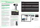
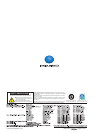
⿎
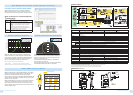
System diagram
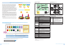
[Actual measurement data for daylight-color LED bulb]
Measured color temperature
Color-temperature difference from
standard-instrument measured value
Our company's standard instrument
5045 0
CL-200A 5011 -34
Photographic color meter 5600 555
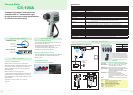
CL-200A
The CL-200A has sensors that closely match the CIE*-dened color-matching functions which are intended to correspond
to the response of the human eye to enable precise color measurement. The measurement results can be displayed in
various color notations such as "Correlated color temperature and
uv" according to the application.
*CIE: International Commission on illumination
Photographic color meter
In order to take more beautiful pictures, it is sometimes necessary to attach lters in front of the camera lens to compensate for
the color of the light illuminating the subject. A photographic color meter is a meter used to select the appropriate lters, with the
sensitivity of its sensors adjusted to match that of the lm or digital camera sensor. In addition, because it uses photographic
color temperature, which is calculated based mostly on the blue/red balance of the illumination, large errors may occur if it is
used to measure light sources with non-continuous spectrums.
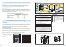
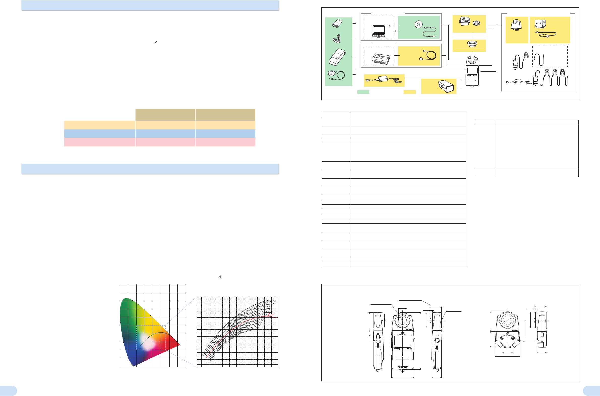
Color temperature
When an ideal blackbody* is heated, it begins to emit light, and as the temperature increases the color of the emitted light
changes from red to yellow to white. Since the color of the emitted light is determined by the temperature of the blackbody, the
color of the light emitted by the blackbody can be expressed as the absolute temperature of the blackbody (in Kelvin). This color
notation scale is called "color temperature". For example, a 7000 K color would be the color of the light emitted by a blackbody
heated to 7000 K. Figure 1 shows the color of light emitted by a blackbody at various temperatures plotted on an xy chromaticity
diagram. This curve is called the "blackbody locus"; "color temperature" expresses a color on this blackbody locus.
Correlated color temperature
Since the color of white light emitted by illumination equipment and displays is generally close to the blackbody locus, the
color of such light sources is normally expressed using "color temperature".
However, the color of such light sources is not directly on the blackbody locus. Because of this, a way to enable similar
color expression for colors within a larger region close to the blackbody locus was devised. This is called "correlated color
temperature", and the larger region is shown by the isotherms on the xy chromaticity diagram in Figure 2.
To accurately express the correlated color temperature of a light-source color, it is necessary to state not only the
correlated color temperature but the difference from the blackbody locus, normally in terms of
uv.
*Blackbody
An ideal radiator. A body which completely absorbs all
incident electromagnetic radiation. Although a perfect
blackbody does not actually exist, coal is a familiar
object that acts similarly.
For accurate measurements of color temperature, use the CL-200A!
Color temperature and correlated color temperature
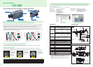
Reference plane
Center of receptor
window
Tripod socket
7.5
7.5
71.8
30
56.346.3
4.5
hole
45.2
50
35
69 30
35
27.5
174
25
45.2
56.318
13
25
Reference plane
Center of receptor
window
Tripod socket
7.5
7.5
71.8
30
56.346.3
4.5
hole
45.2
50
35
69 30
35
27.5
174
25
45.2
56.318
13
25
<Standard accessories>
*
Not included as standard accessory in some areas.
<Optional accessories>
CL-200A
AA Battery (2pcs.)*
Strap
Case T-A10
Cap T-A13
PC
(commercially
available)
RS-232C printer
(commercially available)
Data Management Software
CL-S10w
Processing by computer
Printing out data
USB Cable
T-A15 (2m)
Printer Cable
T-A12 (2m)
AC Adapter
External Power
CL-200A
*
Receptor Head
Hood CL-A11
Optional receptor head
Adapter Unit for
Main Body
T-A20
Adapter Unit for
Receptor Head
T-A21
With LAN category-5 cable 1m
For multi-point measurement / detached head
LAN(10BASE-T )
category-5 straight cable
(commercially
available)
Multi-point measurement requires use of optional AC adapter.
Hard Case
CL-A10
*
CL-200
Receptor
Head can
also be used.
Ex.: Multi-point
measurement
Ex.: Head and body
connected via
cable
Figure 1: Blackbody locus on xy chromaticity diagram Figure 2: Closeup of blackbody locus on xy chromaticity
diagram showing correlated color temperature region
⿎
Main specifications of Data Management
Software CL-S10w
Type Add-in for Excel
®
* Excel is required to use this add-in.
Operating
environment
One of the following environments with Excel
®
installed:
Windows
®
XP Professional 32-bit SP3, 64-bit SP2
+ Excel
®
2003 (English, Japanese, or Simplied Chinese)
Windows
®
7 Professional 32-bit, 64-bit
+ Excel
®
2010 (English, Japanese, or Simplied Chinese)
* For details on system requirements for above versions
of Windows
®
and/or Excel
®
,
refer to their respective specications.
* Languages in parenthesis ( ) are the OS language.
* Not compatible with 64-bit versions of Excel
®
.
Compatible
instruments
CL-200A, CL-200*
* Some functions not usable with CL-200.
⿎
Dimensions
(Units: mm)
With receptor head attached to main body With adapter unit attached to receptor head
Chroma Meter CL-200A Chroma Meter CL-200A