


4 5
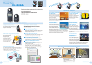
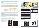
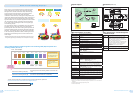
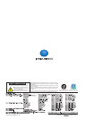
PWM is the abbreviation of Pulse Width Modulation, and refers to
the method of controlling signal intensity by controlling the ratio
between the ON period and OFF period of a pulse signal.
A pulse signal is a signal which repeatedly alternates between ON
and OFF, and the percentage of ON period during a single cycle is
referred to as the "duty cycle".
PWM-controlled lighting is a method for controlling the brightness
of a lamp by controlling the duty cycle (lit time) of light from a
pulse-emission source. As the lit time becomes longer, the light
becomes brighter, and conversely, as the lit time becomes shorter
the light becomes darker.
Period when LED is lit
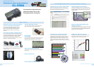
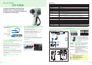
Convenient, easy-to-use Excel
®
add-in software
Reads measurement data from T-10A series Illuminance
Meters directly into Excel
®
. Further processing of data can
then be performed easily using the various functions of Excel
®
.
⿎
Main specifications of Data Management
Software T-S10w
Type Add-in for Excel
®
(Excel
®
is required to use this add-in.)
Operating
environment
One of the following environments with Excel
®
installed:
* Languages in parenthesis ( ) are the OS language.
Windows
®
XP + Excel
®
2003 (English, Japanese, or Simplied
Chinese)
Windows
®
7 + Excel
®
2010 (English, Japanese, or Simplied
Chinese)
* For details on system requirements for above versions of
Windows
®
and/or Excel
®
, refer to their respective specications.
* Not compatible with 64-bit versions of ofce 2010.
Compatible
instruments
T-10A, T-10MA, T-10W
S
A, T-10W
L
A, T-10, T-10M,
T-10W
S
, T-10W
L
Data Management Software T-S10w (Optional accessory)
About PWM-controlled lighting
Relative Spectral Response Cosine Correction Characteristics
Mini plug
Mi
ni C
ap
T-A14
(for T-10MA)
<
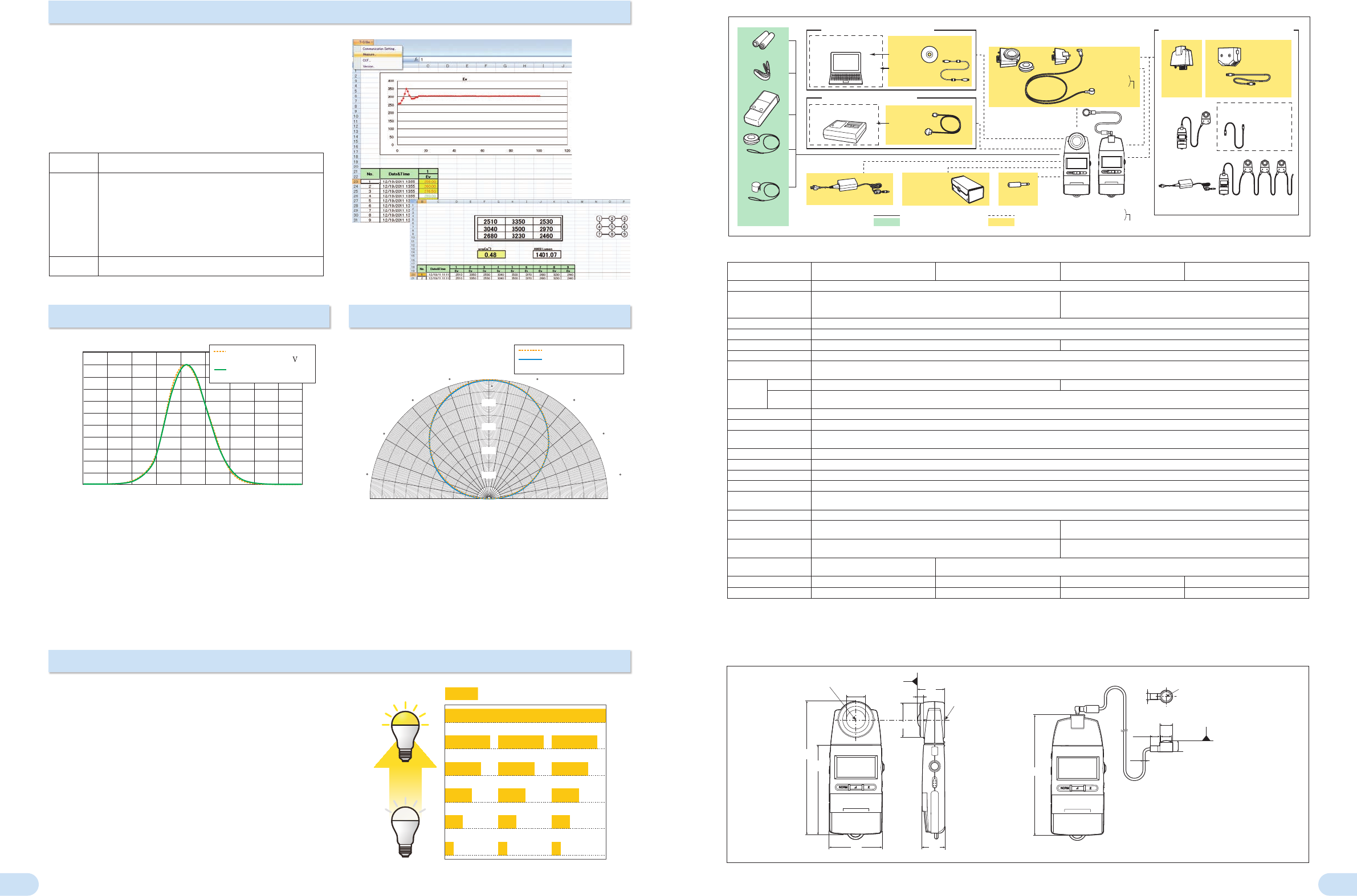
Standard accessories
> <
Optional accessories
>
AA-size batteries
2 pcs.
Strap
Cas
e
T-A10
Ca
p (with Strap)
T-A13
(for T-10A)
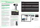
Personal computer
(Commercial product)
RS-232C printer
(Commercial product)
Data Management software
T-S10w
(Including
T-A15)
Data management using computer
Data recording using printer
USB Cable
T-A15
Printer Cable
T-A12
AC Adapter
External power
T-10A
Receptor
Head
Adapter Unit for
Main Body
T-A20
Adapter Unit for
Receptor Head
T-A21
With LAN category 5 cable; 1m
For multi-point and cable extension measurement
Example of
multi-point System
Example of cable
extension
LAN (10 BASE-T)
category 5 straight cable
(commercially
available)
Multi-point measurement requires use of
optional AC adapter.
Hard Case
CL-A10
Hard Case
CL-A10
Additional receptors (sold separately; Product
includes 1 receptor according to model purchased)
Custom models
T-10A
T-10MA
T-10W
S
A
T-10W
L
A
Custom order
T-10MA Receptor Head
T-10W
S
A Receptor Head
T-10W
L
A Receptor Head
⿎
Main Specications of T-10A
Model
Illuminance Meter T-10A
(Standard receptor head)
Illuminance Meter T-10MA
(Mini receptor head)
Illuminance Meter T-10W
S
A
(Waterproof mini receptor head)
Illuminance Meter T-10W
L
A
(Waterproof mini receptor head)
Type Multi-function digital illuminance meter with detachable receptor head (Multi-point measurements of 2 to 30 points is possible)
Illuminance meter class
Conforms to requirements for Class AA of JIS C 1609-1: 2006 "Illuminance
meters Part 1: General measuring instruments" Conforms to DIN 5032 Part
7 Class B
Conforms to requirements for special Illuminance meters of JIS C 1609-1:
2006 *
1
Receptor
Silicon photocell
Relative spectral response
Within 6% (f
1
´) of the CIE spectral luminous efciency V (
λ
)
Cosine response (f
2
) Within 3% Within 10%
Measuring range Auto range (5 manual ranges at the time of analog output)
Measuring function
Illuminance (lx). illuminance difference (lx). illuminance ratio (%). integrated illuminance (lx·h).
integration time (h). average illuminance (lx).
Measuring
range
Illuminance 0.01 to 299,900 lx; 0.001 to 29,990 fcd 1.00 to 299,900 lx; 0.1 to 29.990 fcd *
2
Integrated
illuminance
0.01 to 999,900 x 10
3
lx·h 0.001 to 99,990 x 10
3
fcd·h / 0.001 to 9999 h
User calibration function CCF (Color Correction Factor) setting function: Measurement value x 0.500 to 2.000
Linearity ±2% ±1 digit of displayed value
Temperature/
humidity drift
Within ±3%
Computer interface USB
Printer output RS-232C
Analog output 1 mV/digit, 3 V at maximum reading; Output impedance: 10 KΩ; 90% response time: 28 ms
Display 3 or 4 Signicant-digit LCD with backlight illumination (Automatic illumination)
Power source
2 AA-size batteries / AC adapter AC-A308 (optional; for 1 to 10 receptors) or
AC adapter AC-A311 (optional; for 1 to 30 receptors)
Battery life 72 hours or longer (when alkaline batteries are used) in continuous measurement
Operating temperature
/humidity range
-10 to 40°C, relative humidity 85% or less
(at 35°C) with no condensation
5 to 40°C, relative humidity of 85% or less
(at 35°C) with no condensation
Storage temperature /
humidity range
-20 to 55°C, relative humidity 85% or less
(at 35°C) with no condensation
0 to 55°C, relative humidity of 85% or less
(at 35°C) with no condensation
Dimensions
69 x 174 x 35 mm
Main body: 69 x 161.5 x 30 mm
Receptor: Ø16.5 x 13.8 mm
Cord length
– 1 m 5 m 10 m
Weight (without battery) 200 g (7.0 oz.) 205 g 260 g (Receptor head only: 120 g) 340 g (Receptor head only: 200 g)
*1 Conforms to requirements for Class AA of JIS C 1609-1: 2006 for all items except cosine response (f
2
).
*2 Although measurements below 1.00 lx are possible, they may not be stable due to the effects of electrical noise.
<Notes regarding mini receptors and waterproof mini receptors>
*Do not touch the cable during measurements. Doing so may result in unstable measurement values.
*Secure the cable during measurements. Failure to do so may result in unstable measurement values.
Center of
tripod
socket
Center of
receptor window
Center of
receptor
window
7.5
T-10MA 1 m
T-10W
SA 5 m
T-10W
LA 10 m
25
35
174
117.5
161.5
69
45.2
T-10A
T-10MA/T-10W
SA/T-10WLA
30
16.5
13.613.9
14
Reference
plane
Reference
plane
12.7
3
6.5
Center of
tripod
socket
Center of
receptor window
Center of
receptor
window
7.5
T-10MA 1 m
T-10W
SA 5 m
T-10W
LA 10 m
25
35
174
117.5
161.5
69
45.2
T-10A
T-10MA/T-10W
S
A/T-10W
L
A
30
16.5
13.613.9
14
Reference
plane
Reference
plane
12.7
3
6.5
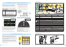
⿎
Dimensions
(Units: mm)
⿎
System diagram
Illuminance Meter T-10A series Illuminance Meter T-10A series
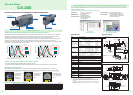
Ideally, the relative spectral responsivity of the illuminance
meter should match V (λ) of the human eye for photopic vision.
As shown in the graph above, the relative spectral responsivity
of Konica Minolta Illuminance Meters T-10A/10MA is within
6% (f1´) of the CIE spectral luminous efciency V (λ).
CIE ; Commission Internationale de I´Eclairage
f1´(CIE symbol) ; The degree to which the relative spectral
responsivity matches V (λ) is characterized by means of the error f1´.
Since the brightness at the measurement plane is proportional
to the cosine of the angle at which the light is incident, the
response of the receptor must also be proportional to the
cosine of the incidence angle.
For Konica Minolta Illuminance Meters T-10A/10MA, the
cosine response f2 is within 3%.
The graph above shows the cosine correction characteristics
of Konica Minolta Illuminance Meters T-10A/10MA.
Relative sensitivity (%)
Wavelength (nm)
Konica Minolta Illuminance
Meters
T-10A/T-10MA
The spectral
luminous efficiency
(λ)
400 450 500 550 600 650 700 750
0
10
20
30
40
50
60
70
80
90
100
60 60
40 40
20 20
0
100
%
80%
60%
40%
20%
80 80
Konica Minolta Illuminance
Meters
T-10A/10MA
Ideal curve