


INSTALLATION MANUAL
H585
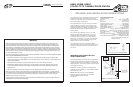
HORIZONTALLY OR VERTICALLY MOUNTING THE H585
In order to install the H585 in the H588,
the H585’s Trim Brackets must first be
mounted to the front of the H588 as
shown.
See Figure 2.
The H585 ships ready for horizontal
installation. Should you choose to mount
the H585 vertically, the H588 must also
be mounted vertically and the camera
module must be rotated 90 degrees.
NOTE: Regardless of the H585’s
orientation, always make sure the wire
protruding from the rear of the camera
module is located in the UPPER-RIGHT
corner when viewed from the rear! See
Figure 3
Once the camera module has been
repositioned, be sure to tighten the
bracket screw, securing the camera in
the desired position.
ADJUSTING THE VIEWING
ANGLE
The camera's viewing angle may also
be adjusted +/- 15 degrees by carefully
twisting the Camera Bracket.
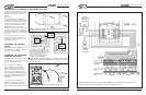
POWERING THE H585 FROM
A REMOTE LOCATION
Most installations will require the H585
be powered from a remote location (i.e.
the main equipment location).
To accomplish this, remove the
power connector from the power
supply (included) and the H585 as
shown to the J-Box wires - be sure
to maintain proper polarity on these
and the remotely located power supply
connections. NOTE: DO NOT remove
the H585 yellow (video) RCA jack
connector!
An "F-to-RCA" barrel connector is
included to facilitate the connection
of RG-6 or RG-59 coax cable to the
H585’s RCA composite video connector.
Figure 2 - Mounting the H585’s Trim Brackets. Note the orientation of
the Trim Bracket’s inner flanges.
1. Use pliers or a 7/16 wrench to loosen
the Set Screw and rotate the camera.
2. Make sure the Camera Wire is located
in the upper right corner when the
H585 is viewed from the rear.
3. Adjust the viewing angle by carefully
twisting the Camera Bracket.
Set
Screw
Camera
Bracket
Camera
Wire
Figure 3 - Whether mounted horizontally or vertically, the Camera Wire
should always protrude from the UPPER-RIGHT corner when the H585 is
viewed from the rear.
18/2 (for Power)
(Remove)
WHITE STRIPE
is POSITIVE (+)
RED = (+)
BLACK = ( - )
To
Video Modulator
12VDC
800mA
Figure 4 - Extending the H585’s power supply cable using 18/2.
Page 2 © 2004 Linear LLC. All Rights Reserved. 08/04 © 2004 Linear LLC. All Rights Reserved. 08/04 Page 3
INSTALLATION MANUAL
H585
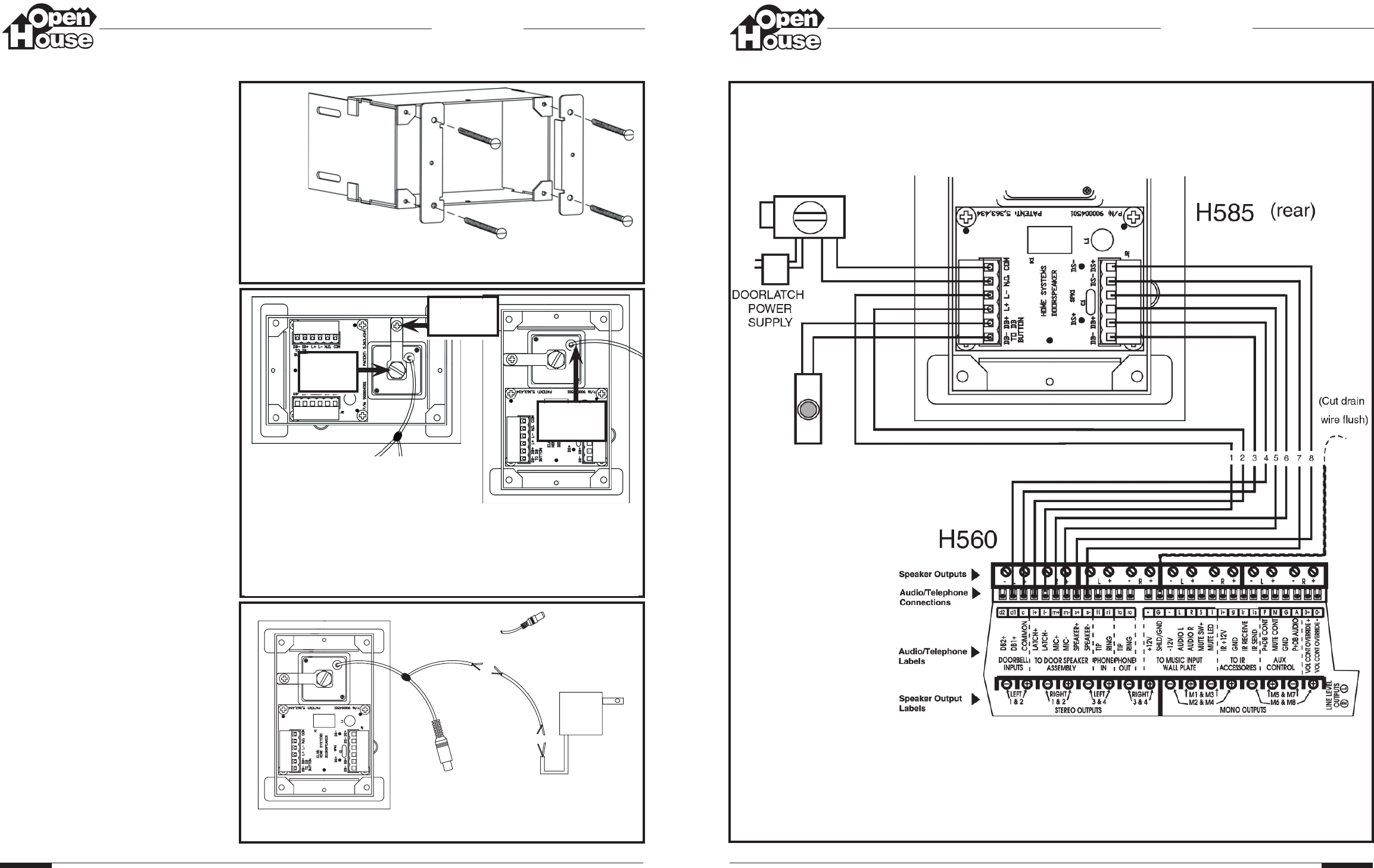
Figure 5 - Connecting the H585 to an H560 amplifier. NOTE: 22 or 24 AWG 4 twisted pair wire with shield is
utilized so the color codes are not called out. Be sure to wire carefully as shown!
BRAND X
ELECTRONIC
DOOR LATCH
MECHANISM
DOORBELL
BUTTON
(INCLUDED)
®
®