


4
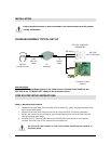
Step 2: Connecting the Camera to the VistaPro4 Digital Video Capture Card
At the location of the PC, plug the other end of the 65’ Camera DIN cable into the DIN
port labeled “To Camera” found on the PT interface module.
Using the 7’ RS-485 Connection Cable, connect the end terminated with the DIN plug to
the port labeled “To DVR” (next to the DIP switches) on the PT Interface module.
On the other end of the RS-485 Connection Cable, screw the single orange wire into the
“TX +” terminal of the ACC-RS232, and the green wire to the “TX –” terminal.
Plug the RCA jack (from the RS-485 Connection cable” into the desired Camera Input
found on the VistaPro4 card.
Connect the ACC-RS232 connector into an available DB9 Comm Port.
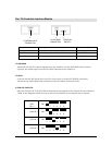
Step 3: Setting the Camera Address
The Dip Switch setting of the camera connected to the PT Interface must correspond to
the RCA Camera Input of the VistaPro 4
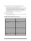
TECHNICAL SPECS: DCP1000 Pan/Tilt Dome Camera
Image sensor 1/4" Color CCD
Active pixels 512(H) X 492(V)
Image sensor area 4.8(H) X 3.7(V) mm
Resolution > 330 TV lines
Min. illumination 1 Lux (F2.0)
Video output 1.0V p-p (75 ohms)
Electronic iris 1/60 ~ 1/100,000 sec
Lens 3.6mm
Synchronization Internal
Signal format 525 lines, 2:1 interlace
System connection 6 Pin Mini DIN jack
Power source DC12V (from interface or controller)
Power consumption MAX. 2.4W
Operating temperature -10°C ~ +50°C
Dimension 126 X 107 mm
Weight 1Kg
Pan/Tilt speed 15° per second
Pan travel 355°
Tilt travel 80°