


Cable Notch
Attach the included BNC to RCA adapter to connect the extension
cable to RCA inputs (i.e. for a TV connection).
BNC to RCA Adapter (Optional)
To Camera: To Monitor/DVR:
Male Power
BNC
Connect the BNC and power
connectors to the camera
Female Power
Connect the BNC connector to
the video input of the monitor /
DVR, and connect the included
power connector to a power
adapter. See Setup Diagram
below for details.
Setup Diagram
ATTENTION - This camera includes an Auto Mechanical IR Cut Filter. When
the camera changes between Day/Night viewing modes, an audible clicking
noise may be heard from the camera. This clicking is normal, and indicates
that the camera filter is working.
1. Twist the ring to tighten/
loosen the stand connection
and adjust the camera’s
horizontal position.
2. Loosen the screw near the stand
and adjust the camera’s vertical
position.
3. If needed, loosen the screw near
the camera and twist the camera
head on the mounting stand.
Before installing the camera:
• Decide whether to run the
cables through the wall /
ceiling (drilling required)
or along the wall / celing.
• If you run the cables along
the wall / ceiling, you
must run the cable through
the cable notch on the
base. This will keep the
camera base flush to the wall / ceiling when mounted.
To install the camera:
1. Set the camera in the desired mounting
position and mark holes for the screws.
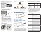
Installing the Camera Connecting the Camera Cable Extension Options
Extend the cable run for your camera up to 300ft or more depending
on the cable type used. See table below:
Option Cable Type Max Cable
Run Distance
Max # of
Extensions
1 Regular BNC
(supplied with camera)
180ft / 55m 3
2 ‘RG59’ or ‘Coax’ or ‘Coaxial
BNC’
(sold seperately)
300ft / 92m 5
3 Lorex Universal Cable
(sold seperately)
300ft / 92m 3
Notes:
1. For optimal performance, consider using option 2 or 3. It is best to use the
same cable type for the entire distance.
2. Cable run recommendation based on typical camera power consumption
(up to 500mA). For specialty cameras with higher current consumption,
maximum cable run may be reduced. Consider providing power to the
camera at the camera side, rather then at the end of the extension cable.
3. Indicators that your cable run may be too long:
• Video is permanently black & white (even during day time)
• Video is distorted
ATTENTION - Test all connections and ensure the camera is working
correctly prior to permanent installation by temporarily connecting the
camera(s) and cable(s) to the viewing / recording solution.
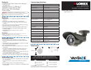
Problem Solution
No picture / signal •Ensure your TV is on the correct input channel.
Common terms of an input channel: INPUT, AV
CHANNEL, LINE1, LINE2, AUX.
•If your camera is connected to a
VCR / DVR, ensure it is properly connected to
your TV / Monitor.
•Ensure connections are properly connected.
•Ensure the camera power supply is plugged in.
Picture is too bright •Ensure your camera isn’t pointed directly at a
source of light (e.g. sun or spot light).
•Slide the sunshade (bullet cameras featuring
adjustable sunshades only) forward to block
excess light.
•Move your camera to a different location.
Picture is too dark •If using during the day, the camera may not
be getting enough light. Slide the sunshade
(bullet cameras featuring adjustable
sunshades only) backwards to let in more light.
•Check the brightness and contrast settings
of the device your camera connects to (TV /
Monitor / DVR).
Night vision is not
working
•The night vision activates when light levels
drop. The area may have too much light.
Picture is not clear •Check the camera lens for dirt, dust,
spiderwebs. Clean the lens with a soft, clean
cloth.
•Make sure that the cable run is within the
limitations specified in the section ‘Cable
Extension Options’.
Bright spot in video
when viewing camera
at night
•Night vision reflects when pointing a camera
at a window. Move the camera to a different
location.
BNC connection does
not connect to my TV.
•Use a BNC to RCA adapter at the end of the
extension cable.
Troubleshooting
2. Drill the holes for the mounting screws.
3. Connect the video and power cables as
shown in the next section ‘Connecting The
Camera‘.
4. Feed the cable through the cable notch (if
running the cables along the wall / ceiling) or
through the mounting surface (if running the
cables through the wall / ceiling).
5. Mount the camera stand to the desired surface
using the provided screws. Make sure all three
screws are fastened tightly at the connection
points.
6. Set the position and angle of the camera using
the provided Allen key.