


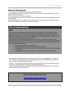
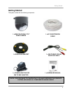

Camera Connections – DIN Cable
6
Camera DIN Extension
Cable
Observation
System Ports
Camera Connections – DIN Cable
NOTE: Visit us on the web at http://www.lorexcctv.com for a full list of compatible Observation Systems.
Before installation make sure that:
• You have the proper lift equipment or ladder to reach the installation location.
• Electrical power is not connected to the dome camera and surveillance monitor during installation.
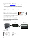
DIN Installation
NOTE: The camera will only work on CHANNEL 1 when using the DIN Cable connection.
1.) Conne
ct the 60 ft Din cable (included with the dome camera) to the wired lead of the dome camera.
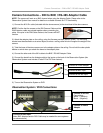
NOTE: Confirm that the arrows on the DIN Camera Cable and the
DIN Extension cable are pointed together when connecting the
cable. If the pins in the DIN Connector are bent, the Camera will
NOT function.
2.) Attach the adaptor plate on the ceiling using the 3screws
provided (M3X20 screw). The mounting bracket must be attached to a structural object, such as a ceiling
rafter which will support the weight of the camera.
3.) Twist the base of the dome camera on to the adaptor plate on the ceiling. Do not hold the clear plastic
bubble or swivel when you attach the dome to the adapter plate.
4.) Connect the other end of the 6
0 ft cable to the CH1 DIN Camera Input on the back of the Observation
System (the System must include a Pelco-D Pan/Tilt Zoom feature).
5.) Turn on the Observation System.
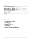
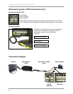
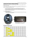
DIN – Port Pins
A. Video Input
B. Audio Out
C. NC (Not Connected)
D. B+ 12V ( Power )
E. Audio Input
F. Camera Audio AMP: B+ 12V ( Power )
G. Ground