


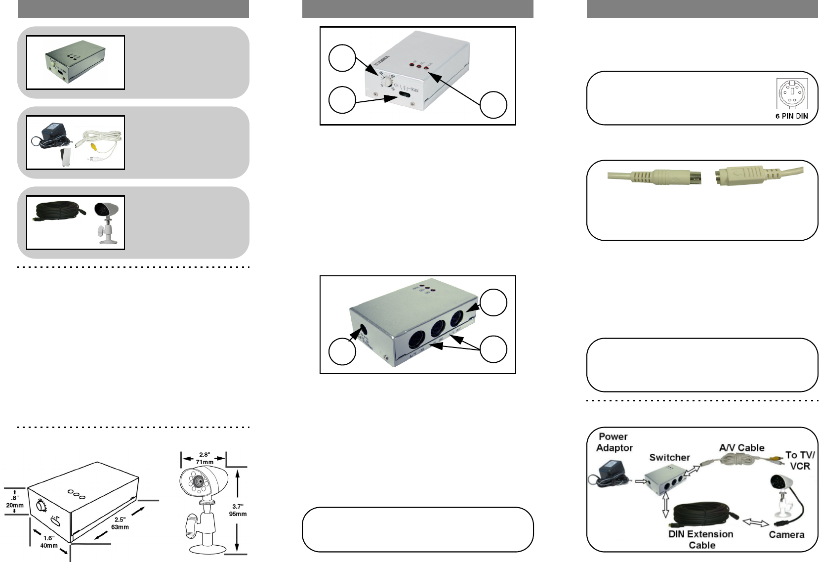
1. Connect the 60ft (18m) DIN Extension cable to the
Switcher. Run the cable as desired, and connect the
other end of the 60ft (18m) Extension Cable to the DIN
Camera (see Setup Diagram below).
2. Attach the camera to the supplied stand. Mount the
camera stand to the desired mounting surface
3. Connect the DIN end of the A/V Cable to the switcher.
Connect the RCA end to the corresponding color ports
on the TV or VCR:
•Yellow Cable: RCA Video
•White Cable: RCA Audio
4. Connect the Power Adaptor to the switcher.
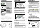
Switcher Features:
• Easily connects to any TV, VCR or Monitor
• Compact design
• Easy mounting with Velcro strip (included)
Camera Features:
• Durable Metal Camera ideal for indoor or outdoor use *
• Night Vision provides viewing in low light conditions **
• View as well as listen with camera's built-in
microphone.
* Not recommended for direct exposure to rain or snow
** IR illumination range of 8ft. / 2.5m under ideal conditions. Objects at or be-
yond this range may be partially or completely obscured, depending on the
camera application.
1. Package Contents 2. Switcher Controls 3. Camera Connections
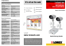
1 x Mini Switcher Box
1. SCAN TIME SETTING - Turn to adjust the lenth of time
that each camera is displayed onscreen before switching to
the next camera. The sequence time can be set between
1~30 Seconds (when in SCAN View Mode).
2. CHANNEL SELECT - Move the switch to change the
onscreen view to CH1, CH2 or SCAN View Mode.
3. STATUS INDICATOR LEDs - The Red LED light
indicates that the unit is in Scan Mode; The Green LED
lights indicate the currently displayed channel (CH1 or
CH2).
4. DC POWER PORT - Connection port for the Power
Adaptor.
5. A/V OUT DIN PORT - Sends the outgoing video/audio
signal to a TV or VCR.
6. CH1~CH2 DIN PORTS - Receives the audio and video
signal from the Cameras.
1 x Power Adaptor
1 x AV Cable
1 x Velcro Adhesive Strip
NOTE: Cameras with 6 Pin DIN
connections draw power from the Switcher.
Additional power adaptors are not needed
for these cameras.
2
3
1
6
5
4
Setup Diagram:
NOTE: Confirm that the arrows on the DIN Extension
cable are aligned with the Camera Cable and Observation
system ports when connecting the cable. If the pins in the
DIN Cable are bent, the Camera will NOT function
2 x DIN Cameras
2 x Camera Stands
2 x 60’ Extension Cables
Dimensions:
NOTE: Test the cameras prior to selecting a
permanent mounting location by temporarily
connecting the Cameras and Cables to the switcher.
NOTE: This camera is designed to work with a 9V
Power Adaptor ONLY. Use of this camera with any
other system may damage the camera and invalidate
the warranty.