


1
Product Overview
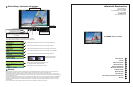
The V-R70DP is the successor to the V-R70P. Signifi cant improvements over the previous model include our completely digital
TFT-Megapixel™ high resolution TFT/LCD screen with 1.2 million pixels, V-Mount battery adapter, 4 pin XLR power jack, and
optical grade polycarbonate screen protection. All signals are digitized to provide the truest representation of your captured video
images. Convenient front panel controls provide fast access to all functions for this model that accepts Two Composite plus One
S-Video signal.
2
Features
2
5
V-R70DP
V-R70DP
Users Guide
Users Guide
Marshall Electronics
High Defi nition Display • Capable of displaying more than 800 TV Lines resolution. Standard defi nition is internally up
converted to High Defi nition. All signals remain completely digital to provide the most exact images
available.
Standard Inputs • Two Analog Composite with PAL/NTSC Auto Detect with passive lop through
• Y/C (S-video)
Durable metal enclosure • Protection for all connections and controls with strategically placed ventilation for use in harsh
environments
Protective Screen Cover • Optical grade polycarbonate screen cover with Antirefl ective/Antiglare coating
Memory Function • Adjustment Settings Memory stored on shutdown and recalled when power is applied.
Blue Gun • Use for adjustment to SMPTE color Bars
V-Mount Battery Adapter • Use virtually any battery system used in the fi eld today
OSD • On Screen Display to provide instant feedback of adjustments and settings
Tally (DB-15) • Three LEDs (Red, Green, Amber) produce 7 different tally indications
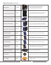
Camera Hot Shoe Mount V-LCD4-MT Attaches monitor to camera
Stand V-LCD4-ST Use for table top mount
Sun Hood V-H7M Use for viewing in bright lighting or outdoors
Power Adapter Cable V-PAC-D Use with Anton Bauer D-type connection
Power Adapter Cable V-PAC-XLR Use with 4 Pin XLR connections
4
Optional Accessories
3
Standard Accessories
Accessories Supplied with the V-R70DP
• Users manual
• “Brick” type 12vdc power supply with 4 Pin Female XLR connector
• “V” Mount battery adapter
• ¼”-20 mounting plate
210 Plastic Cleaner & Polish and 210 Plus Cleaner
Sumner Laboratories
186 Lincoln Street
Boston, MA 02111
617-542-8656 / Fax: 617-482-9001
20/20 Plastic-Cleaner
Craftics, Inc.
PO Box 91930
Albuquerque, NM 87199
(505) 338-0005
Crystalclean
Discovery Plastics
3700 Western Way, NE
Millersburg, OR 97231
541-926-2900 / Fax: 541-967-8441
www.discoveryplastics.com
Plexus Plastic Cleaner
Plexus
638 Lindero Canyon Rd. #371
Agoura, CA 91301
800-405-6495
Fax: 818-879-0697
Scotch-Brite High Performance Cloth
3M Stationery & Offi ce Supplies Div.
3M Center
St. Paul, MN 55144-1000
877-362-5684
Fax: 651-733-0382
www.mmm.com
NOVUS #1 Plastic Clean and Shine
NOVUS, Inc.
12800 Highway 13 South, Suite 500
Savage, MN 55378
800-548-6872 ext.451
Fax: 952-946-0435
The Simco Industrial Static Control
An Illinois Tool Works Co.
2257 North Penn Road
Hatfi eld, PA 19440-1998
800-203-3419
215-822-2171
Fax: 215-822-3795
www.simco.biz
Exair Corporation
1250 Century Circle North
Cincinnati, OH 45246-3309
513-671-3322
Fax : 513-671-3363
www.exair.com
Recommended Anti-Static Cleaners and Polishes
8
Operational Setup
1. Unpack the V-R70DP and accompanying power supply. Physically inspect for any damage that may have occurred during ship-
ping. Should there be any damage, immediately contact Marshall Electronics at 800-800-6608. If you are not located within the
continental united states call +1 310-333-0606.
2. Connect required cables for signal input and output. All BNC connectors should be rated for 75..
3. Plug the power supply into the A.C. source
Please note that power can be supplied from a variety of DC sources, such as batteries or Vehicle power. Input power range is
10.7 to 15 Volt D.C.
In operation, the V-R70DP will draw approx. 0.8 amp.
Attach 4 Pin XLR power connection from V-PS12-V-5 power supply to the back of the unit.
4. Turn on the V-R70DP by depressing the power switch located on the front of the unit.
9
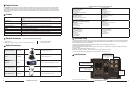
Input Connectors
Battery and External Power can
not be used simultaneously
V-Mount Battery Adapter See
Optional Accessory section for a
selection of batteries
* Tally lamps active when connected to ground
Composite
Video In
Termination Switches and
Video outputs
Non Loop through of composite video
requires termination switch set to the
75 position. For loop through set to
HiZ position
S-Video In
4 Pin Din (Female)
Pin1 - GND
Pin2 - GND
Pin3 - Yin
Pin4 - Cin