


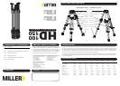
The 2 Transport Clips (Fig.3) are designed to hold the HD tripod’s three
legs together during transport. Their spring-loaded design means they
are easily gripped and detached
for set up, and just as easily
snapped back on to the
legs for transporting tripod.
The Transport Clips must be
securely attached before
transporting the tripod.
TRIPOD SET-UP
TRIPOD PULL DOWN
SPREADER
CARRY HANDLE
LEG LOCK ADJUSTMENT
TRANSPORT CLIPS
SAFETY
MAINTENANCE
1. Before setting-up the tripod, the Mid Level Spreader must be
attached.
2. Remove tripod from the Softcase and unclip the Transport Clips.
3. Place the Tripod Feet on level surface (if possible) and release the
Quik Lok Upper Lever on each leg.
4. Lift the top of the tripod to a desired height and then apply the Quik
Lok Upper Lever on each leg.
5. Release the Quik Lok Lower Lever on each leg (2-Stage model),
then lift the tripod to a desired height and apply the Quik Lok Lower
Lever on each leg.
6. Spread the Tripod Legs apart, check that the Tripod Bowl is
approximately level to the ground.
7. Check that the tripod is secure.
Remove the camera from the Fluid Head.1.
Retract the spreader arms fully. 2.
Hold and lift off the ground by two legs, then bring the legs inwards.3.
While holding the top of the tripod, release the Quik Lok Upper Lever 4.
and Quik Lok Lower Lever (2-Stage model) on each leg then lower
completely.
Apply the Quik Lok Upper Lever and Quik Lok Lower Lever on each 5.
leg.
Attach both Transport Clips and return the tripod to the Softcase.6.
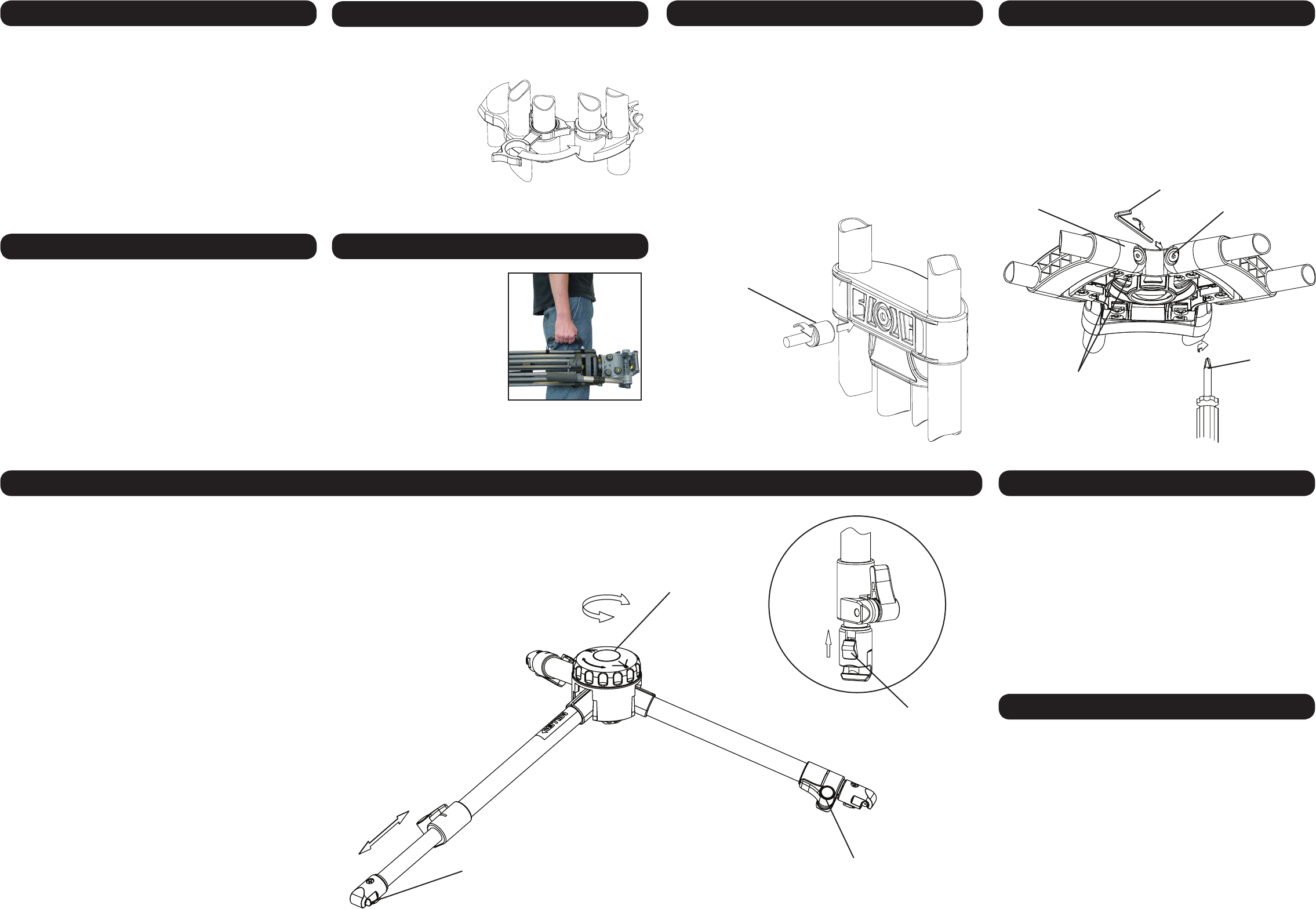
Mid Level Spreader (Fig 7.)
The Mid Level Spreader allows the setting of the Tripods footprint and
ne height adjustment. The tripod height and overall footprint can be ad-
justed by turning the Spreader Adjusting knob or by adjusting the length
of the telescopic spreader arms.
Spreader Set-up
1. Turn the Spreader Adjusting Knob counter-clock wise to the open
position.
2. Stand the Tripod upright with legs spread out equally.
3. Release the Telescopic Clamp on the spreader arm then latch the
Quick Release Latch on to the Pivoting Spreader Mount, repeat for
the remaining two arms.
4. Bring each Tripod leg in such that the corresponding Spreader arm is
fully retracted then lock the Telescopic Clamp, repeat for each
Spreader arm.
5. Bring the Tripod legs towards the centre position, if resistance is felt
do not force the Tripod legs, spread out the Tripod legs and make
sure that the Spreader arms are fully retracted.
Spreader Pull Down
1. Remove the Camera and the Fluid Head from the Tripod.
2. Stand the Tripod upright with legs spread out equally and the Mid
Level Spreader in the open position.
3. Pull back the Quick Release Latch knob (Fig 8.) and lift the Spreader
arm from the Pivoting Spreader Mount, repeat for the remaining two
arms.
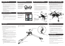
Miller’s 2- part Carry Handle
(patented) (Fig 4.) is perfectly
positioned to balance the tripod
with the head attached.
NOTE: 1-Stage & 2-Stage 100mm
tripod models only.
Ensure that all equipment is operating correctly and free from defects
and damage, also please ensure that the tripod is steady, secure and
that the bowl is approximately horizontal when attaching the camera.
The operator is responsible for the safe operation of this equipment.
1. Do not exceed the maximum payload capacity of the Tripod.
2. Do not leave the camera unattended on the Fluid Head.
3. Do not adjust the tripod Leg locks whilst the camera is attached to
the Fluid Head.
4. Do not move the Tripod whilst the camera is attached to the Fluid
Head.
5. Do not remove the Mid Level Spreader or Ground Spreader whilst
the camera and uid head is attached.
Regularly inspect the tripod, paying particular attention to any tube
damage, leg lock adjustment, leg top adjustment, condition of the bowl
rim, spreader mounting points, carry handle and feet.
Keep grit and dirt out of Sprint Loks as much as possible, including
behind levers. Regularly clean the tripod with a clean damp rag or soft
brush. Wipe off all sand, dust and salt spray.
Do not clean with solvents, cleaning uids, lubricants, polishes, abra-
sives or wire brushes.
Transport and store the tripod in Miller case wherever possible. Store the
tripod in a dry place, away from direct sunlight.
Quick Release Latch knob
Over time the leg locks may need adjusting to prevent leg slippage.
Adjust the Upper Leg Lock Assembly in a locked position using 13mm
Socket. (Fig 5.)
Extend the upper stage half way and lock the Upper Lever.1.
Turn the Upper Leg lock adjuster clockwise 1/8th of a turn. Release 2.
Sprint Lok Upper Lever and ensure that stage slides freely.
When adjusted correctly Leg Lock Lever should only have a small 3.
amount of “free play” before locking action commences. If this free
play is excessive repeat the steps above.
WARNING:
ALWAYS ADJUST WITH LEVER
IN LOCKED POSITION. ADJUST
LOCK IN SMALL INCREMENTS.
DO NOT OVER-TIGHTEN.
(Upper leg lock illustrated)
13mm SOCKET
LEG TO BOWL ADJUSTMENT
The leg to bowl pivot joint on the HD tripod should have no lateral or free
play movement and should swing with a rm, smooth resistance. Adjust-
ment is usually not required, however, should it become necessary, the
following procedure must be observed. (Fig 6.)
Leg to Bowl Adjustment to eliminate lateral, or free play movement: 1.
Using a cross head screwdriver, ensure Bracket Mounting Screws on
both sides of the Leg Top Bracket are tight. Retighten if necessary.
Check all legs.
Leg pivot or ‘swing’ adjustment to ensure rm, smooth resistance. 2.
Tighten the Leg Pivot Screws on each side of the Leg Top Bracket
using a 4mm allen key until a smooth resistance is maintained. Check
all legs.
Leg Top Bracket
4mm Allen Key
Leg Pivot Screw
Bracket Mounting
Screws
#2 Pozi Head
Screw Driver
Fig 4.
Fig 3.
Fig 5.
Fig 6.
Fig 7.
MID LEVEL SPREADER
Spreader adjusting knob
Fig 8.
Quick Release Latch
Telescopic clamp