


4
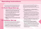
Before using please read the following operating instructions.
Do not omit any step. N.B. The safe operation of this piece of
professional equipment is the responsibility of the operator.
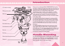
1.1 Loosen the PAN HANDLE CLAMP fully, then rotate the PAN
HANDLE until it is approximately perpendicular to the
THREADED STUD and tighten the PAN HANDLE CLAMP -
avoid contact wear between the serrations on the Fluid
Head and the PAN HANDLE CLAMP, if this occurs then
unwind the PAN HANDLE CLAMP further.
1.2 Ensure that the TRIPOD BOWL is approximately horizontal.
Place the Fluid Head into the TRIPOD BOWL, adjust the
BUBBLE LEVEL such that the bubble is inside the black
circle and tighten the CLAMP NUT.
1.4 Note: If adjusting the level with your camera mounted,
first ensure the camera is securely held before loosening
CLAMP NUT.
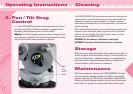
Please note that the best camera control can be achieved by
balancing camera centre of gravity (C of G) over centre axis of
the head, and by selecting the appropriate counterbalance
position to suit the weight of the camcorder payload.
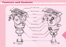
The DS5/DS10/DS20 is equipped with a sliding camera plate and
a removable 1/4”-pin carriage which is standard mounting for DV
and MiniDV camcorders. The DS20 is also fitted with a 3/8” &
1/4” screws which is standard mounting for DVCAM (see Fig1.3).
The 3/8” & 1/4” screws also allow the DS20 to attach to a
proprietary Quick Release Tripod Adaptor or “tripod base plate”
such as the Sony VCT-14 or Panasonic SHAN-TM700.
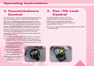
2.1 Lock PAN and TILT LOCKS (rotate both levers clockwise until
firm).
2.2 Remove CAMERA PLATE from CAMERA PLATFORM by
unlocking the SLIDE LOCK, pushing SAFETY TAB and sliding
the CAMERA PLATE rearward
2.3 With accessories and battery fitted to the camera, it is
recommended to estimate the camera’s Centre of Gravity (C
of G) for the purpose of correctly positioning the camera on
the CAMERA PLATE. The camera’s C of G can be estimated by
placing the camera on to a round rod and then shifting it
backwards or forwards until a balance point – C of G - is
achieved. It is recommended to identify this point as it will be
useful in step 2.5.
2.4 Refer to the Camera’s owners manual for correct method of
attachment to the CAMERA PLATE. Attach the camera or the
Quick Release Tripod Adaptor to the CAMERA PLATE and
securely tighten the screws.
2.5 Check that the SLIDE LOCK is loose, then align the
CAMERA PLATE with the CAMERA PLATFORM and
slide it forward until the safety mechanism is engaged.
Then, slide the CAMERA PLATE so that the camera’s C of G
is directly above the centre axis of the Fluid Head and tighten
the SLIDE LOCK. If this can not be achieved then reposition
the camera or the Quick Release Tripod Adaptor on the
SLIDING PLATE – step 2.4. This will ensure that the system
has maximum stability.
2. Camera Set-up
Operating Instructions
1. Fluid Head Set-up