


Ground Spreader (Fig 6.)
The Miller Ground Spreader provides telescoping adjustment of each spreader
arm to allow for lower height settings or uneven ground.
Set up
1. Set the tripod in the desired location.
2. Pull two legs outwards until Ground Spreader is lying on the
supporting surface
3. Extend telescoping arms if required to reposition individual tripod legs
Pull Down
1. Close tripod by pulling Ground Spreader up by centre ring. Ensure all
spreader telescoping arms are either fully retracted or adjusted to
exactly the same length before closing the tripod legs.
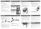
Lower Leg Lock: (Fig 8.)
For 2 stage Sprinter II Tripod only.
Adjust the Lower Leg Lock Assembly in locked position using a (supplied)
5mm Hex Key. - P6579
1. Extend the lower stage half way and lock the Lower Lever.
2. Tighten the adjusting screw gradually clockwise 1/8th of a turn.
Release Lower Lever and ensure leg slides freely.
3. When adjusted correctly Leg Lock Lever should only have a small
amount of “free play” before locking action commences. If this free
play is excessive repeat the steps above.
When nished, ensure that all Leg Lock Levers
lock ush with the tripod brackets.
Test each leg lock assembly by:
· Unlocking and locking lever several times.
· The lever should close with a denitive ‘click’.
· The end of the lever should close against the bracket.
· The tripod legs must slide freely when unlocked.
A Mid Level or Ground Spreader allows for rapid tripod setup and pull down
by keeping tripod legs at an equal or preset distance relative to each other.
A Mid Level Spreader attaches to the centre bracket of a tripod leg, while a
ground spreader attaches directly to the tripod feet.
Mid Level Spreader (Fig 5.)
The Miller Mid Level Spreader provides for continuous variable adjustment
between maximum and minimum height settings. The tripod height and
overall footprint can be adjusted by turning the Height Adjustment knob or
by adjusting the length of the telescopic spreader arms.
Setup
1. Set the tripod feet to the desired location – you may need to screw
the Height Adjustment Knob SCREW OUT or adjust the length of the
spreader arms to do this.
2. Screw the Height Adjustment Knob SCREW IN until resistance is felt.
3. Pull two legs outwards slightly to ensure stable stance of tripod.
Pull Down
1. Before closing the tripod, ensure all spreader arms are either fully
retracted or adjusted to exactly the same length before closing the
tripod legs. If a quick release latch is stuck, undo the spreader arm
telescoping clamp to release tension on the latch.
GROUND SPREADER
Adjustment Knob
TRIPOD SET-UP
TRIPOD PULL DOWN
SPREADERS
CARRY HANDLE
TRANSPORT CLIPS
SAFETY
MAINTENANCE
Remove tripod from carry case and stand on a level surface
(if possible). Unclip the 2 transport clips located on the lower tube section
of the tripod.
Single Stage Sprinter II Tripod
(one Sprint-Lok per leg to control lower stage).
1. Holding top of tripod, use thumb and forenger to open (disengage)
the Sprint-Lok lever on each tripod leg.
2. Extend the tripod to the required height then
close (engage) the Sprint-Lok levers. Ensure the feet are at on the
ground.
3. Spread the tripod legs fully apart and repeat (1) to ensure the tripod
bowl is approximately level.
4. Adjust the Mid Level or Ground spreader if required (see Spreader
section)
5. Gently pull two legs outwards, to make the tripod more stable.
6. Level the uid head using the Bubble Level and ball leveling feature
of the uid head.
2-Stage Sprinter II Tripod
(2 Sprint Loks per leg to control mid and lower stage).
1. The 2 Sprint Loks on each leg can be opened (disengaged)
independently or simultaneously.
2. Proceed as per Single Stage tripod setup instructions.
Note: On 2-Stage tripods, optimum rigidity is achieved when mid and low-
er tripod stages are both extended equally to achieve the desired height.
1. Remove camera payload from uid head.
2. Close the tripod, ensuring rst that the spreader telescopic arms are
exactly the same length before fully closing the tripod legs.
3. Open (disengage) all Sprint Loks while holding the top of the tripod
and with tripod feet on the ground, then fully lower the tripod to its
shortest length.
4. Close (engage) all Sprint Loks.
5. Re-attach 2 transport clips.
6. Return tripod to carry case if nished shooting.
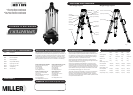
The Sprinter II Inline patented Carry
handle (g 4.) is designed so the
Sprinter II tripod and uid head remain
balanced while being carried by hand.
The rubber handle offers secure grip,
while the exible nylon attachments let
it rest, between the tripod legs, during
shooting.
The 2 Transport Clips (Fig 3), are de-
signed to hold the Sprinter tripod’s three
legs together during transport. Their
spring-loaded design means they are
easily gripped and detached for set up,
and reattached.
READ THE OPERATOR’S MANUAL
Miller recommends that all camera support equipment should be carried in
a reinforced carry case
All Miller Sprinter II systems include a reinforced carry case that protects
the tripod from impact damage and limits exposure to heat and moisture
during carriage and storage.
Ensure the weight of the payload does not exceed the specied capacity.
Never set up or pull down a tripod while a camera is mounted on it.
Ensure all Tripod/Spreader locks are securly engaged prior to mounting
camera.
The safe operation of the tripod is the responsibility of the operator.
Regularly inspect the tripod, paying particular attention to any tube dam-
age, leg lock adjustment, leg top adjustment, condition of the bowl rim,
spreader mounting points, carry handle and feet.
Keep grit and dirt out of Sprint Loks as much as possible, including behind
levers. Regularly clean the tripod with a clean damp rag or soft brush. Wipe
off all sand, dust and salt spray.
Do not clean with solvents, cleaning uids, lubricants, polishes, abrasives
or wire brushes.
Transport and store the tripod in Miller case wherever possible. Store the
tripod in a dry place, away from direct sunlight
LEG LOCK ADJUSTMENT
Over time the leg locks may need adjusting to prevent leg slippage.
Upper Leg Lock: ( Fig 7.)
For Single & 2 stage Sprinter II Tripod.
Adjust the Upper Leg Lock Assembly in a locked position using (supplied)
5mm Hex Key - P6579.
1. Extend the upper stage half way and lock the Upper Lever.
2. Turn the Upper Leg lock Nut clockwise 1/8th of a turn. Release Upper
Lever and ensure that stage slides freely.
3. When adjusted correctly Leg Lock Lever should only have a small
amount of “free play” before locking action commences. If this free
play is excessive repeat the steps above.
Transport Clip
Telescopic Clamp
Quick Release Latch
Height Adjustment Knob
MID LEVEL
SPREADER
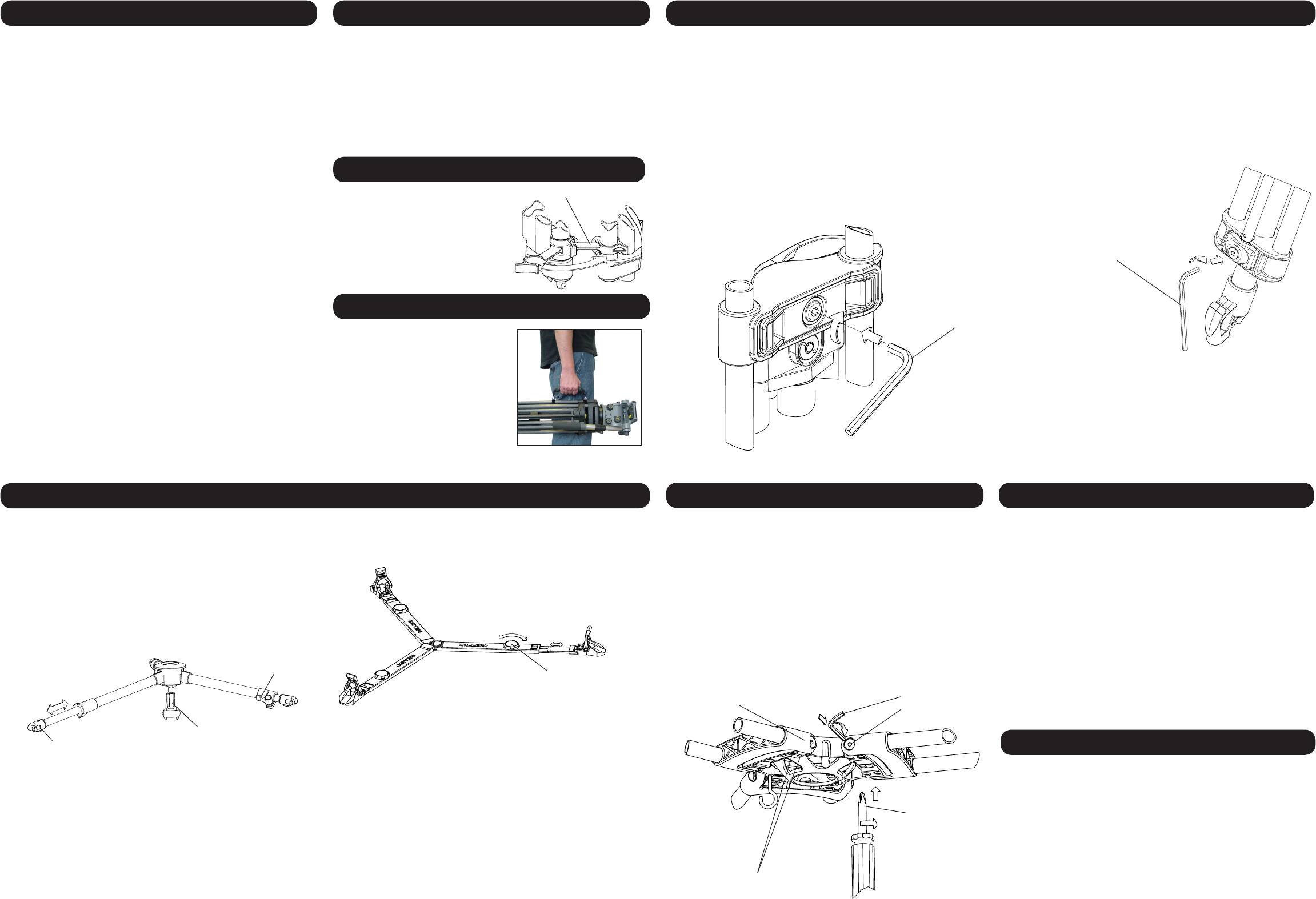
LEG TO BOWL ADJUSTMENT
The leg to bowl pivot joint on the Sprinter tripod should have no lateral or
free play movement and should swing with a rm, smooth resistance.
Adjustment is usually not required; however, should it become necessary,
the following procedure must be observed. (Fig 9.)
1. Leg to Bowl Adjustment to eliminate lateral or free play movement:
Using a cross head screwdriver, ensure Bracket Mounting Screws
on both sides of the Leg Top Bracket are tight. Retighten if neces
sary. Check all legs.
2. Leg pivot or ‘swing’ adjustment to ensure rm, smooth resistance.
Tighten the Leg Pivot Screws on each side of the Leg Top Bracket
using a 4mm Hex key until a smooth resistance is maintained. Check
all legs.
Leg Top Bracket
4mm Hex Key
Leg Pivot Screw
#2 Pozi Head
Screw Driver
Bracket Mounting
Screws
Fig 5.
Fig 6.
Fig 4.
Fig 3.
Fig 7.
Fig 9.
5mm Hex key
5mm Hex key
Fig 8.