


7
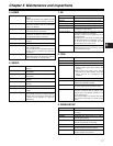
Chapter 7 Menu description tables
81
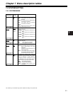
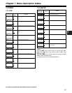
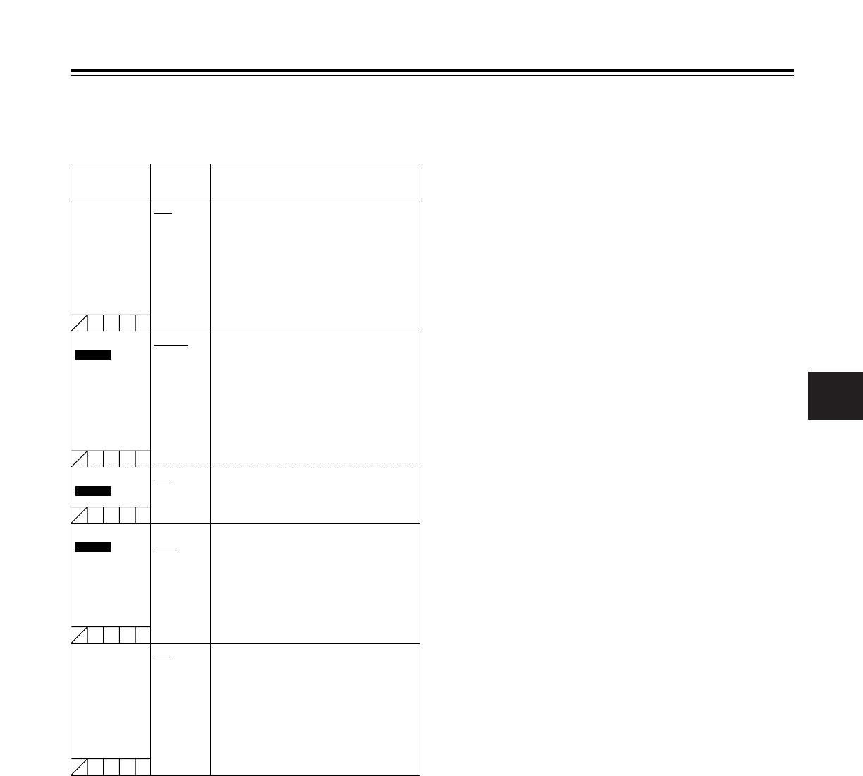
REC TALLY RED
GREEN
CHAR
For selecting the method used to inform the
user that the unit is recording when a system
using an extender or other device is
configured and BOTH is selected as the 26-
PIN CONTROL menu item setting while the
system is used in the remote control mode.
RED: The red tally lamp lights.
GREEN: The green tally lamp lights.
CHAR: The letters “REC” appear on the
viewfinder.
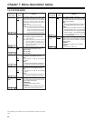
Item/
Data storage
Variable
range
Remarks
PB MODE
SDC905
MANUAL
AUTO
For selecting the playback mode.
MANUAL
: The playback mode accords with the
25M or 50M setting of the REC
MODE item.
Operation proceeds with 16:9 or 4:3
read from the tape.
AUTO: In this mode, the recording mode is
automatically detected and playback
is performed in the same mode.
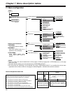
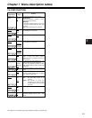
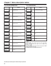
7-2 SYSTEM SETTING
7-2-1 SYSTEM MODE
The underlining in the variable range column indicates the setting in the preset mode.
REC SIGNAL CAM
VIDEO
1394
For selecting the video input signals.
CAM: The signals from the camera are
recorded.
VIDEO: The signals from the GENLOCK IN
connector are recorded.
1394: The signals from the DVCPRO
connector are recorded.
<Note>
CAM is always set when the power is next
turned on after it being turned off.
CUFE
CUFE
CUFE
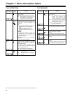
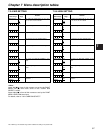
REC MODE
SDC905
16:9/50M
4:3/50M
16:9/25M
4:3/25M
For selecting the mode in which to record the
signals on the VTR.
16:9/50M: <16:9> signals are recorded at 50
Mbps.
4:3/50M: <4:3> signals are recorded at 50
Mbps.
16:9/25M: <16:9> signals are recorded at 25
Mbps.
4:3/25M: <4:3> signals are recorded at 25
Mbps.
CUFE
ASPECT
SDC615
16:9
4:3
For selecting the mode in which to record the
signals on the VTR.
16:9: <16:9> signals are recorded.
4:3: <4:3> signals are recorded.
CUFE