


-5-
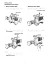
1 Not used
Not used
GND
Not used
Not used
+12V IN
+5V IN
FOCUS CONT
ZOOM CONT
Not used
+7.5V IN
+2.5V IN
2
3
4
5
6
7
8
9
10
11
12
Speed
Low High
4.0V 2.5V
6.0V 7.5V
4.0V 2.5V
6.0V 7.5V
NEAR
FAR
WIDE
TELE
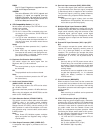
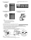
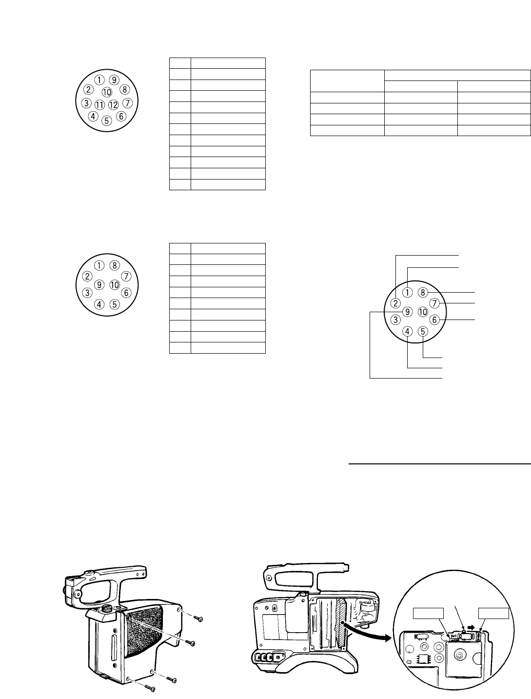
■ Lens Connector (19)
• EPin configuration
1 GND
COM (0V)
Not used
LEFT
RIGTH
UP
DOWN
DEFROSTER
WIPER
Not used
2
3
4
5
6
7
8
9
10
<Front View>
<Front View>
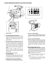
■ Pan/Tilt Control Connector (20)
• Pin configuration
Note:
Be sure to follow the conditions indicated below.
1. Functions are active at the Low control voltage.
2. Open Collector Output (Withstand voltage of
Transistor is maximum 30 V.)
3. Current is maximum 20 mA.
• Control Voltage (each voltage is ±0.5V.) for the
lens.
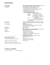
White
Yellow
Green
Glay
Brown
Red
Purple
Blie
■ Optional Pan/Tilt Control Cable
WV-CA10U25
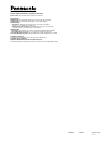
Audio System Operation with the optional Remote Control Unit
The audio output to the Remote Control Unit WV-RC700A is available in the VP Multiplex operation.
1. Connect a coaxial cable between the Remote Control Unit WV-RC700A and Power Separator WV-PS700.
2. Connect the Multiplex Output Cable on WV-PS700 to the Multiplex Signal Input Connector (15) on this adaptor.
3. Set the Audio Level Selection Switch (11) to the –20 dB position.
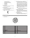
4. Remove four screws from the side cover of this adaptor.
5. Set the Switch 1 on the Audio board inside this adaptor to the AUDIO position.
6. Set the Switch 2 on the MOD board inside the Remote Control Unit WV-RC700A to the AUDIO position.
Notes:
1. At this time, the intercommunication system cannot function.
2. The Switch 1 on the Audio board is preset to the INCOM position at the factory.
Remove four Screws.
SW1
(Set this switch to
AUDIO position.)
INCOM AUDIO