Security Cautions
When using this product, take appropriate measures to avoid the following
security breaches.
• Disclosure of private information via this product
• Unauthorized use of this product by a third party
• Interference or suspension of the use of this product by a third party
You are responsible for the security of this product and its use. Take the
following measures to avoid security breaches.
• To prevent unauthorized access, disclosure of private information, or
interference or suspension of access to the camera, make sure the
camera’s firmware is up to date.
• Do not reveal the user names and passwords required to access the
camera to an unknown party.
• If you choose to configure this product to allow access to parties without
the need to enter a user name and password (i.e., guest users), be
aware that unknown parties may access this product.
• Do not upload images produced by this product or otherwise release
information where it may be accessed by unknown parties.
• Mount the camera where the camera will not be stolen.
• When sending this product for service or transferring this product to
another party, make backup copies of its setup files, and reset this
product to its factory default settings.
• When disposing of this product, reset the product to its factory default
settings.
User Name and Password Protection
The use of unique user names and secret passwords is an important
tool that will help limit unauthorized individuals from accessing the
camera. If you choose to disable this tool by allowing guest (i.e.
anonymous) access, the camera may be accessed by unauthorized
individuals.
Audio and Video Recording Notice
Please note that under certain circumstances, audio/video recording may
be prohibited by law. This device should be used only in compliance with all
applicable laws and statutes.
MPEG-4 Visual License
This product is licensed under the MPEG-4 Visual patent portfolio license
for the personal and non-commercial use of a consumer for (i) encoding
video in compliance with the MPEG-4 Visual Standard (“MPEG-4 Video”)
and/or (ii) decoding MPEG-4 Video that was encoded by a consumer
engaged in a personal and non-commercial activity and/or was obtained
from a video provider licensed by MPEG LA to provide MPEG-4 Video. No
license is granted or shall be implied for any other use. Additional
information including that relating to promotional, internal and commercial
uses and licensing may be obtained from MPEG LA, LLC.
See http://www.mpegla.com.
About the MPEG-4 Viewer Program
The MPEG-4 viewer program is an ActiveX
®
Control that is used to play
MPEG-4 files within Internet Explorer. This software is installed
automatically the first time you view MPEG-4 videos.
A software license for the MPEG-4 decoder is included with the MPEG-4
viewer program, and the license is valid for 1 PC. Please read the included
End-User License Agreement before installing the viewer program. When
installing the MPEG-4 viewer program on additional PCs, please purchase
additional licenses (Model No. BB-HCA5A).
About the OpenSSL License
This product includes software developed by the OpenSSL Project for use
in the OpenSSL Toolkit. (http://www.openssl.org/) This product includes
cryptographic software written by Eric Young. (eay@cryptsoft.com)
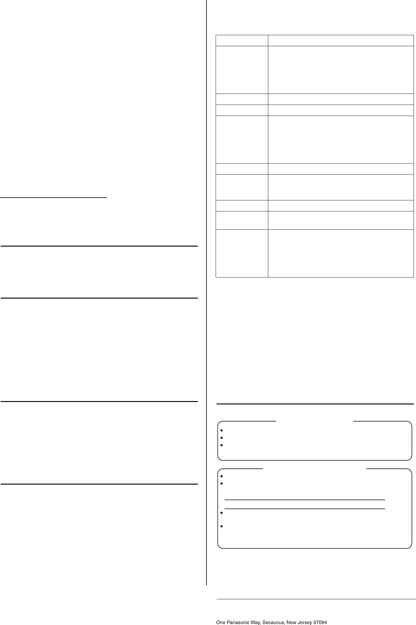
System Requirements
Your PC and network must meet the following technical specifications in
order for the camera to function properly.
*1 What is IPv6?
• IPv6 is short for “Internet Protocol Version 6”.
• IPv6 was created to provide the additional IP addresses that will be
needed as the Internet continues to expand.
• IPv6 is expected to gradually replace IPv4, with the 2 coexisting for a
number of years during a transition period.
• Though most ISPs (Internet Service Providers) do not yet support IPv6,
many local networks already use it. When your ISP supports IPv6, your
Panasonic Network Camera will be ready!
• For more information, visit http://www.ipv6.org/.
Note:
Refer to the Panasonic Network Camera website at
http://panasonic.net/pcc/support/netwkcam/
for details about network environment.
Item Requirement
Operating
System
For IPv4 Connection
Microsoft
®
Windows Vista
®
, Windows
®
XP,
Windows 2000
For IPv6 Connection
*1
Microsoft Windows Vista,
Windows XP Service Pack 1 or later
CPU 2.0 GHz Celeron
®
or faster
Display 1024 x 768 resolution or higher
Protocol For IPv4 Connection
TCP/IP protocol (HTTP, TCP, UDP, IP, DNS, ARP,
ICMP)
For IPv6 Connection
TCP/IP protocol (HTTP, TCP, UDP, IP, DNS, ICMPv6,
NDP)
Interface 10/100 Mbps network card
Wireless
Interface
(BL-C121 Only)
IEEE 802.11b/g (Embedded)
Web Browser Internet Explorer
®
6.0 or later (not included)
Audio PC speaker or headphones (required to use the
Listen feature)
Additional
Software (For
Viewing Buffered
MPEG-4 Images)
For Windows Vista
Windows Media
®
Player 11 or later
For Windows XP
Windows Media Player 9 or later
For Windows 2000
Windows Media Player 9
When You Ship the Product
Panasonic Service Centers are listed in the Service Center directory.
Call 1-800-272-7033 for the location of an authorized Service Center.
This product is designed for use in the United States of America. Sale or
use of this product in other countries/areas may violate local laws.
Carefully pack your unit, preferably in the original carton.
Attach a letter, detailing the symptom, to the outside of the carton.
Symptom
Send the unit to an authorized Service Center, prepaid and adequately
insured.
Do not send your unit to the Panasonic Consumer Electronics Company
listed below or to executive or regional sales offices. These locations do
not repair consumer products.
For Product Service
Trademarks
• Microsoft, Windows, Windows Vista, ActiveX, Internet Explorer, and Windows Media are
either registered trademarks or trademarks of Microsoft Corporation in the United States
and/or other countries.
• Celeron is a trademark or registered trademark of Intel Corporation or its subsidiaries in
the United States and other countries.
• All other trademarks identified herein are the property of their respective owners.
The information in this document is subject to change without notice.
Copyright:
This material is copyrighted by Panasonic Communications Co., Ltd., and may be reproduced
for internal use only. All other reproduction, in whole or in part, is prohibited without the written
consent of Panasonic Communications Co., Ltd.
Panasonic Consumer Electronics Company,
Division of Panasonic Corporation of North America


