


Copper wire
size (AWG)
Copper wire
size (AWG)
Length
of Cable
(Approx.)
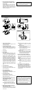
CONNECTIONS
A. WV-BP140 (120 V AC 60 Hz)
Connect the power cord to an electrical outlet
of 120V AC 60Hz.
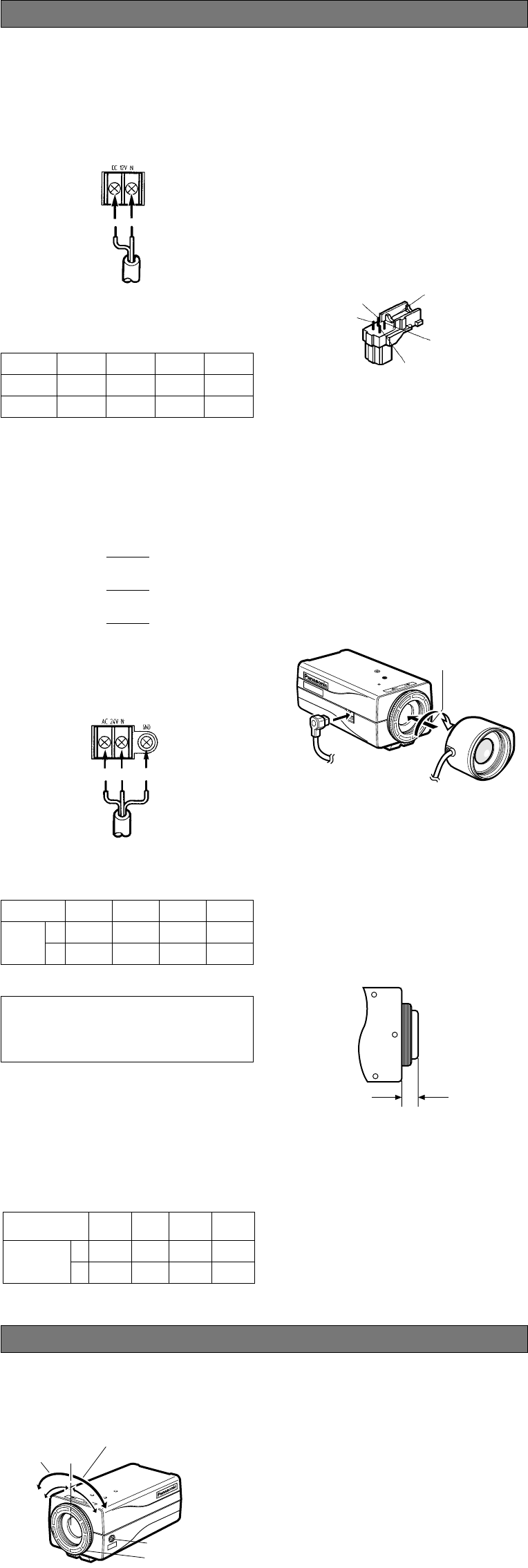
B. WV-BP142 (12 V DC)
Connect the power cord to the DC 12V IN ter-
minal on the rear panel of the WV-BP142.
Resistance of copper wire [at 20°C (68°F)]
• Calculation of maximum cable length
between camera and power supply :
Resistance
Ω/m
Resistance
Ω/ft
#24
(0.22mm
2
)
0.078
0.026
#22
(0.33mm
2
)
0.050
0.017
#20
(0.52mm
2
)
0.03.
0.010
#18
(0.83mm
2
)
0.018
0.006
10.5V DC ≤ V
A
− (R x 0.42 x L) ≤ 16 V DC
L : Cable length (meters)
R : Resistance of copper wire (Ω/meter)
VA : DC output voltage of power supply unit
VA − 12
L standard = (meters)
0.42 x R
VA − 16
L minimum = (meters)
0.42 x R
VA − 10.5
L maximum = (meters)
0.42 x R
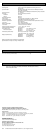
The following adjustment should be made by
qualified service personnel or system installers.
q Loosen the screw on the side of the camera.
w Turn the flange-back adjusting ring to the
desired position.
Caution: When the C-mount lens is mounted,
do not rotate the ring counterclockwise
by force after it stops. If the ring is rotat-
ed by force, the inner lens or CCD image
sensor may be damaged.
e Tighten the screw on the side of the camera.
Caution: Tightening the screw by force will
cause damage to the screw or deviation
of focus.
FOCUS OR FLANGE-BACK ADJUSTMENT
12 V DC
(10.5 V - 16 V)
@
!
C. WV-BP144 (24 V AC 60 Hz)
Connect the power cable to the AC 24V IN
terminal on the rear panel of the WV-BP144.
(m)
(ft)
#24
(0.22 mm
2
)
95
314
#22
(0.33 mm
2
)
150
495
#20
(0.52 mm
2
)
255
842
#18
(0.83 mm
2
)
425
1 403
Recommended wire gauge sizes for 24 V AC line
24 V AC, 60 Hz
(19.5 V - 28 V)
1 2
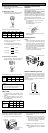
Installation of Auto Iris Lens
Connector
Install the lens connector (YFE4191J100) when
using a video drive ALC lens.
The installation should be made by qualified
service personnel or system installers.
Cut the iris control cable at the edge of the lens
connector to remove the existing lens connector
and then remove the outer cable cover of the sup-
plied connector as shown in the diagram.
The pin assignment of the lens connector is as fol-
lows:
Pin 1: Power source; +9 V DC, 50 mA max.
Pin 2: Not used
Pin 3: Video signal; 1.3 V[p-p]/40 kΩ
Pin 4: Shield, ground
Pin 3
Pin 4
Pin 2
Rib
Pin 1
Mounting the Lens
Caution:
Before you mount the lens, loosen the screw
on the side of the camera, and rotate the
flange-back adjusting ring clockwise until it
stops. If the ring is not at the end, the inner
lens or CCD image sensor may be damaged.
q Mount the lens by turning it clockwise on the
lens mount of the camera.
w Connect the lens cable to the auto iris lens
connector on the side of the camera.
Focus Fixing Screw
w
q
cs
c
Caution for Mounting the Lens
The lens mount should be a C-mount or CS-mount
(1”-32UN) and the lens weight should be less than
450 g (0.99 lbs). If the lens is heavier, both the
lens and camera should be secured by using the
supporter.
The protrusion at the rear of the lens should be as
shown in the diagram.
C-mount: Less than 13 mm (1/2”)
CS-mount: Less than 8 mm (5/16”)
Solder the lens cable to the pins of the sup-
plied connector.
Flange-back
Adjusting Ring
Focus Fixing Screw
Focusing of
C-mount lens
Focusing of
CS-mount lens
LOCK
Caution:
To prevent fire or electric shock hazard, use
a UL listed cable (VW-1, style 1007) for the
DC 12 V or AC 24 V Input Terminal.
Video Cable
1. It is recommended to use a monitor whose
resolution is at least equal to that of the
camera.
2. The maximum extensible coaxial cable
length between the camera and the moni-
tor is shown below.
Type of RG-59/U RG-6U RG-11/U RG-15/U
coaxial cable (3C-2V) (5C-2V) (7C-2V) (10C-2V)
Recommended (m) 250 500 600 800
maximum
cable length (ft) 825 1 650 1 980 2 640