


11
10
F
R
O
N
T
LOC
K
F
R
O
N
T
F
R
O
N
T
LOC
K
F
R
O
N
T
Projections
Hooks for the
decorative cover
*1 position on the
rear side
START
END
FRONT
FRONT
LOCK
Mounting base
Camera mounting plate
Align A with A
Align B with B
Fixing screw to be used for cover fall prevention
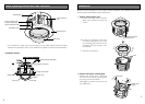
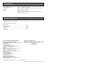
14. Mount the camera mounting plate on
the mounting base.
q Align the marks (A to A and B to
B) between the camera mounting
plate and mounting base.
w Mount the camera mounting plate on
the mounting base with aligning g of
the camera mounting plate with
"STARTh" of the mounting base.
e Turn the camera mounting plate until
g of the camera mounting base
aligns with "ENDh" of the mounting
base.
r Tighten the 3 screws that were
removed in Step 2.
(Recommended tightening torque:
1.6 N·m {16 kgf·cm})
Important: Do not let the cables be
caught during installation work.
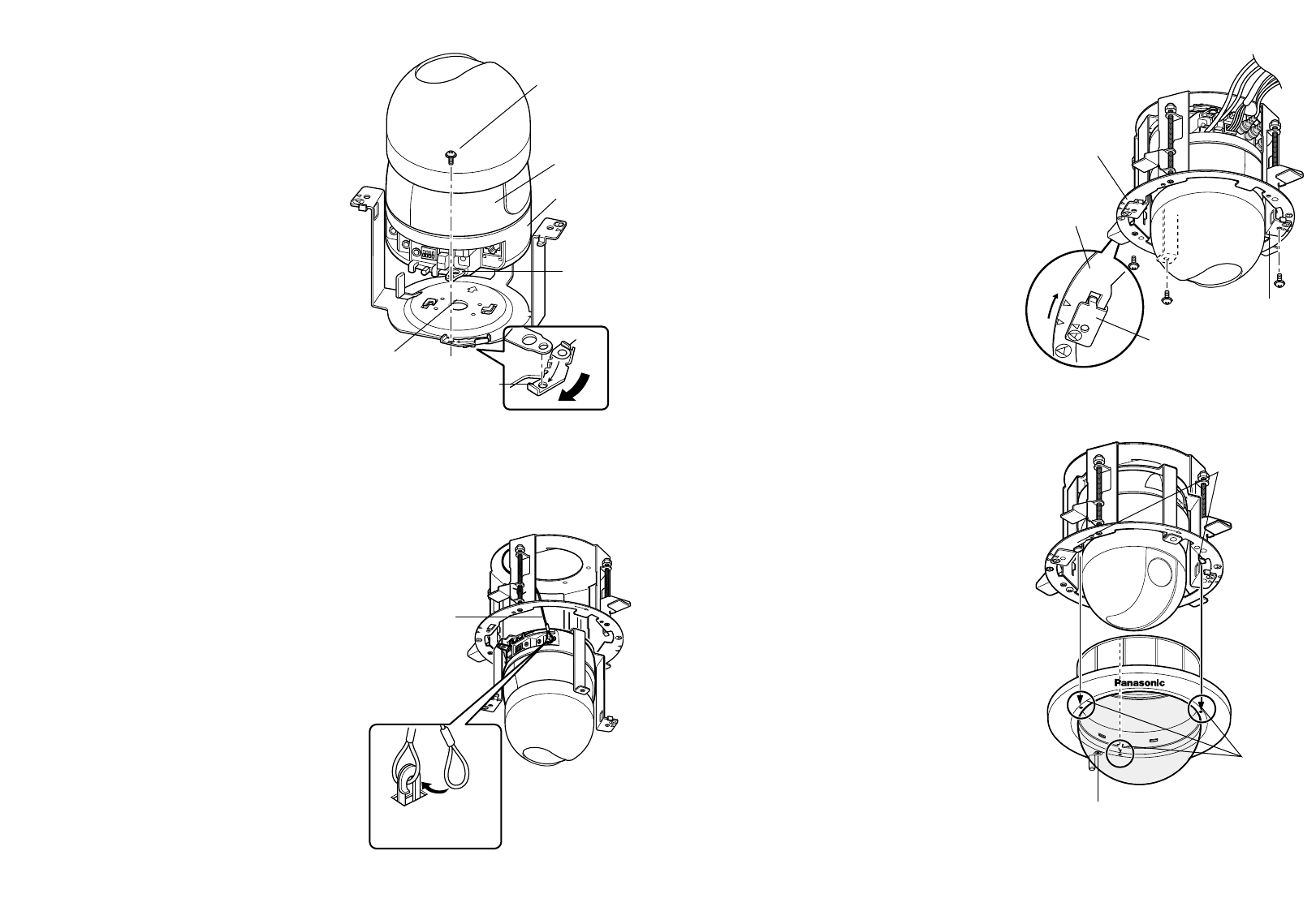
15. Mount the decorative cover.
q Mount the decorative cover on the
camera mounting plate with engag-
ing the projections of the decorative
cover with the hooks for the decora-
tive cover.
w Turn the decorative cover clockwise
while pressing the projections
upward and the cover is locked.
Important: The mark, "FRONT", shall be
aligned with the Panasonic logo.
16. Tighten the fixing screw to be used for
cover fall prevention.
(Recommended tightening torque:
1.6 N·m {16 kgf·cm})
F
R
O
N
T
FRONT
L
O
C
K
Mounting base
Safety wire
FRONT
LOCK
Stationary portion
Center of the
camera mounting
plate
Camera fixing
screw
Lock plate
Guide
Rotating portion
Safety wire hook
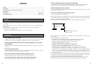
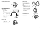
11. Mount the camera on the camera
mounting plate.
q Put the camera onto the camera
mounting plate with aligning the lock
plate of the camera with the guide of
the camera mounting plate and
aligning the center of the camera
mounting plate with the center of the
screw for tripod mounting, and turn
the camera clockwise.
w Secure the camera with 1 piece of
the camera fixing screw (supplied
with the camera).
(Recommended tightening torque:
0.68 N·m {7.0 kgf·cm})
Important: Be sure to mount the camera
with holding the stationary portion of
the camera. Camera mounting with
holding the rotating portion of the
camera may cause trouble.
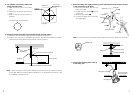
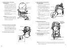
12. Connect the safety wire to the camera.
q Connect the safety wire locked on
the mounting base to the camera.
Make sure that the apical ring of the
safety wire is engaged with the safe-
ty wire hook of the camera by pulling
the safety wire after connection.
13. Connect the cables to the camera.
Note: When the camera lens is pointed in the horizontal direction, the inner shell interferes
with the camera’s view, and consequently about upper half of the monitor screen is
hidden in the WIDE mode.