


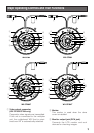
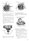
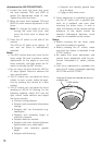
■ Disassembling the Camera
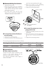
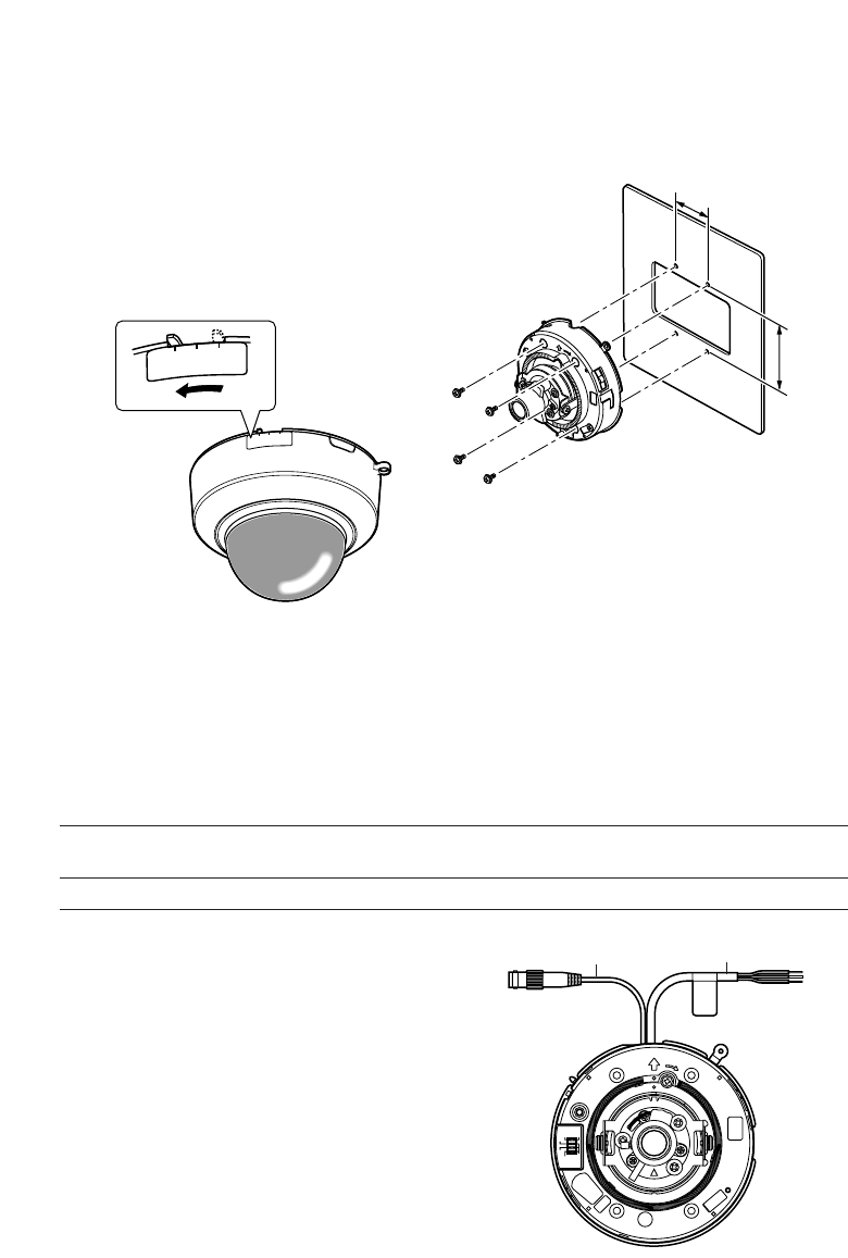
1. Remove the top cover.
• Adjust the marker of this unit to "INSERT"
of the "DOME COVER" label on the top
cover and turn the top cover counter-
clockwise to remove it.
• The clear dome cover and the inner
dome cover are joined into a single unit.
Therefore, never try to remove them.
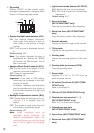
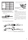
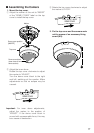
● To mount the camera directly on
the wall/ceiling
1. Prepare the mounting space.
2. Place the camera on the wall/ceiling and
D
O
M
E
C
O
V
E
R
L
O
C
K
A
D
J
U
S
T
I
N
S
E
R
T
DOME COVER
LOCK
ADJU
ST
INSERT
mark four screw positions with a pen.
3. Mount the camera on the wall/ceiling
with 4 screws (procured locally).
4. Fasten all the mounting screws.
● To mount the camera on a two-
gang junction box
1. Install the two-gang junction box on the
wall/ceiling.
2. Mount the camera on the two-gang junc-
tion box with 4 screws (procured local-
ly).
3. Fasten all the mounting screws.
TOP
LOOK
46 mm {1-13/16"}
Camera mounting screw x4
(not supplied)
83.5 mm
{3-5/16"}
12
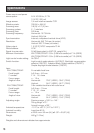
Mounting place
Ceiling/wall
Model
(direct mounting)
Recommended
screw
M4
Number of
screws
4 pcs.
Minimum pull-
out strength
196 N {20 kgf}
The mounting requirements are shown as follows.
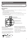
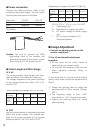
■ Connections
● Video output connection
Connect the video output connector to the
monitor or other system devices with the
procured coaxial cable or LAN cable.
The maximum extensible cable length is
shown in the table.
LOCK
TOP
Video output connector Power cable
<WV-CF284>
BLC
ALC
ELC
B.S
D/N
ON
OFF