


Troubleshooting
8-7
9783-A2-GB20-00
July 2000
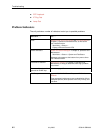
Alarms
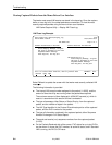
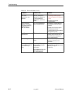
The following table describes the alarm conditions that will generate an SNMP
trap for a physical interface, and the frame relay LMIs and DLCIs. These alarm
conditions also generate Health and Status messages seen on the System and
Test Status screen.
Main Menu
→
Status
→
System and Test Status
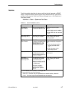
Table 8-1. Alarm Conditions (1 of 4)
Alarm Condition
What It Indicates What To Do
CTS down to
Port-1
Device
The CTS control lead on
the device’s interface is off.
Check DTR and RTS from
Port-1.
H Verify that the port is enabled.
H Check DTR from the user data
port.
DLCI
nnnn
Down,
frame relay link
1,2
The DLCI for the specified
frame relay link is down.
Verify that the network LMI is up.
If it is, contact your network
service provider.
DTR Down from
Port-1 Device
The DTR control lead on
the device connected to the
specified port is off. This
message applies to data
ports that act as DCEs.
Examine the attached DTE and
cable connected to the system’s
port.
H Check that the port cable is
securely attached at both
ends.
H Check the status of the
attached equipment.
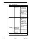
Ethernet Link Down The communication link for
the Ethernet port is down
and the Interface Status for
the port is enabled.
Check the LAN connected to the
Ethernet port.
Link
Down
Administratively,
frame relay link
2
The specified frame relay
link has been disabled by
the unit due to LMI
Behavior conditions or LMI
Protocol on another link is
in a failed state.
This is not an alarm
condition so System
Operational appears,
as well.
Verify that the network LMI is up.
If it is, contact your network
provider.
1
nnnn
indicates a DLCI number of 16 through 1007.
2
frame relay link
is one of the following:
– Net1-FR1. The frame relay link specified for the network interface, Network 1.
– Port-1. The frame relay link associated with the user data port.