


INSTALLATION
Remove the dust covers from the lens. Remove any dust with a soft brush or clean compressed air.
The lens is installed by carefully threading it clockwise onto the mount of the CCTV camera
until fully seated. If the lens has a coupling ring, tighten it against the camera. Use a
C/CS-mount adapter if attaching a C-type lens to a CS-type camera. The PCMA40 adapter is
available from Pelco.
Plug the four-pin electrical connector into the camera auto-iris DC drive or auto-iris video drive
socket, whichever is applicable.
Follow the camera operating instructions for iris and focus adjustments.
Perform tracking (backfocus) adjustment after lens installation or if your camera system does
not maintain sharp focus throughout the lens zoom range:
(1) Select an object as a focusing target at a distance of 75-100 feet (23-31 m) from the
camera system.
(2) Set the lens focus for extreme far (infinity).
(3) Open the iris (aperture) to the fully opened position.
(4) Zoom the lens out to the extreme wide angle. Adjust the camera imager for the best focus.
Refer to the camera manufacturer’s instruction sheet for the imager adjustment procedure.
(5) Zoom the lens in to the extreme telephoto. Adjust the lens focus (do not adjust the
camera imager) for the sharpest picture.
(6) Zoom the lens out to the extreme wide angle and check for sharp focus. Repeat steps 4
and 5 until the focus is sharp throughout the entire zoom range.
Lenses having ALC and LEVEL variable resistors may need the following adjustments:
(1) ALC (Light Metering)
This function allows a variable selection of light metering between average (A) and peak
(P). Turn the variable resistor on the lens body with a precision screwdriver (not provided)
until suitable exposure is obtained.
(2) LEVEL (Image Signal)
This feature helps to adjust the brightness of the images projected
on the TV monitor. When it is necessary to make a correction due
to camera characteristics or lighting conditions, adjust the variable
resistor on the lens body with a precision screwdriver (not provided)
until optimum level is obtained.
ROUTINE SERVICING
Never touch the surface of either lens.
Remove dust from the lens by using a soft brush or clean compressed air. Avoid touching the
lens surface during handling.
To remove fingerprints or oil stains from the lens surface, use lens cleaning paper or a clean
cotton cloth with a little cleaning liquid. Then, wipe off the stains using a light circular motion,
starting from the center of the lens surface. Wipe the lens body with a silicon cloth. Do not use
any organic solvents such as thinner or benzene.
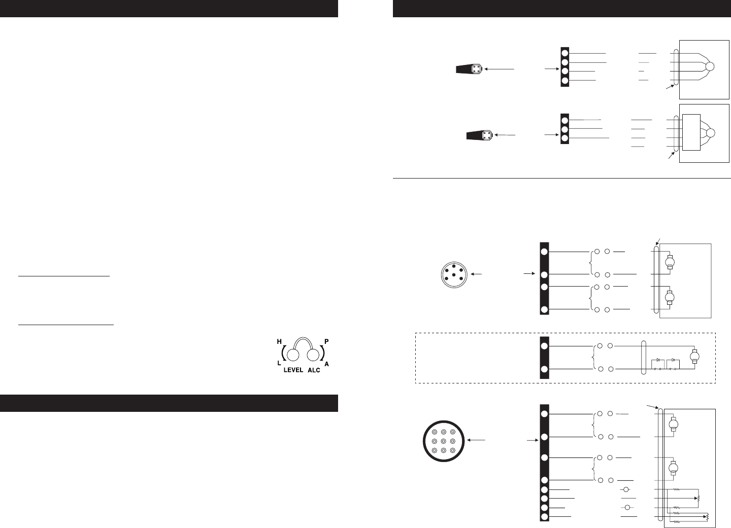
ALC & Level
Adjustment Screws
1
3
4
2
RED
BLACK
YELLOW
GREEN
G
IRIS
4-PIN
SQUARE
CONNECTOR
TO CAMERA AUTO-IRIS SOCKET, DC DRIVE
4 2
3 1
DRIVE ( + )
DRIVE ( – )
CONTROL ( – )
CONTROL ( + )
4-CONDUCTOR CABLE
AUTO-IRIS PLUG PIN-OUT
(REAR OF PLUG, SOLDER LUGS)
1
3
4
RED
BLACK
WHITE
GREEN
G
IRIS
TO CAMERA AUTO-IRIS SOCKET,
VIDEO DRIVE
AUTO-IRIS PLUG PIN-OUT
(REAR OF PLUG, SOLDER LUGS)
4 2
3 1
DC+(8-16)
GROUND
REMOTE
VIDEO
AUTO-
IRIS
CIRCUIT
4-CONDUCTOR CABLE
4-PIN
SQUARE
CONNECTOR
Pelco ZD
Type
Lenses
Pelco ZV
Type
Lenses
6-PIN AND 9-PIN LENS CONNECTORS
Note: Unless customer specified, Pelco will no longer supply 6-pin Hirschmann or 9-pin
AMP connector assemblies.
4
3
2
4
6
7
8
9
2
5
8
3
6
97
4
1
TO ZOOM/FOCUS CONTROLLER
ZOOM-FOCUS PLUG
(REAR OF PLUG, CRIMP SIDE)
9-PIN AMP
CONNECTOR
+ ( – )
YELLOW
+ ( – )
– ( + )
– ( + )
RED
GREEN
BLACK
BROWN
GRAY
WHITE
BLUE
M
M
FOCUS RETURN
PRESET COMMON
ZOOM RETURN
PRESET SUPPLY
WIDE > TELE
(TELE > WIDE)
FAR > NEAR
(NEAR > FAR)
ZOOM
FOCUS
5K
5K
1K
1K
1K
1K
+
–
10-CONDUCTOR CABLE
4
3
2
4
2
5
3
6
4
1
TO ZOOM/FOCUS CONTROLLER
ZOOM-FOCUS PLUG PIN-OUT
(REAR OF PLUG, SOLDER LUGS)
+ ( – )
YELLOW
+ ( – )
– ( + )
– ( + )
RED
GREEN
BLACK
M
M
WIDE > TELE
(TELE > WIDE)
FAR > NEAR
(NEAR > FAR)
ZOOM
FOCUS
10-CONDUCTOR CABLE
4
1
IRIS WIRING FOR PELCO
ZM TYPE LENSES (ONLY)
+ ( – )
WHITE
– ( + )
BROWN
M
CLOSE >OPEN
(OPEN > CLOSE)
IRIS
6-PIN HIRSCHMAN
CONNECTOR
LIMIT SWITCH
LENS AND CONNECTOR WIRING DIAGRAMS
FOUR PIN LENS CONNECTOR