


Pelco Manual C1488M-B (2/99) 13
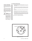
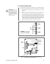
3.4 BACK BOX CONNECTIONS
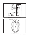
Depending on the type of dome, refer to either Figure 10 or 11 to attach the wiring to the
interconnect circuit board inside the back box. Also refer to Figure 6 or 7 if necessary.
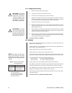
1. Earth Ground - Connect earth ground to the middle connector on the power
connector.
2. Power - Connect 24 VAC from the transformer to the outer terminals on the
power connector. It does not matter which lead goes to which terminal.
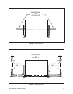
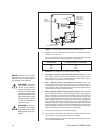
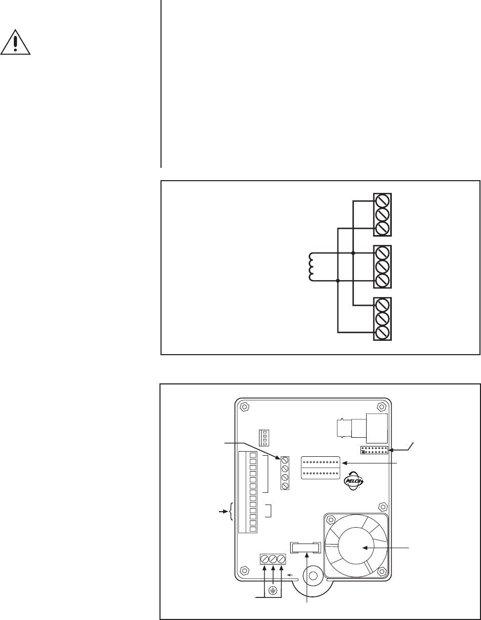
If you are wiring more than one dome from the same transformer, it is impor-
tant to wire the power connector in each dome the same way. That is, the
wiring from one side of the transformer must be connected to the same con-
nector on each dome. If you reverse the wiring, the cameras will be out of
phase with each other and may produce what appears to be vertical roll when
switching between cameras. Refer to Figure 9 for a wiring diagram.
3. Video - Connect the coaxial cable to the BNC video connector.
WARNING:
Make sure
you wire power to the
outer connectors of the
terminal block and ground
to the middle connector.
Otherwise, you could
damage the dome.
Figure 10. Interconnect Circuit Board Electrical Connections for
Spectra™ (Ver. 3.0) and Spectra II™
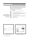
Figure 9. Transformer Wiring
EXAMPLE:
If each dome
requires 20 vA, three domes
require a 60 vA transformer.
DOME 1
POWER
DOME 2
POWER
DOME 3
POWER
HTR/FAN
RX–
RX+
TX–
TX+
PWR IN
FUSE
1.6 A
DOME DRIVE
CONNECTOR
RS-422
CONTROL
SIGNALS
1
2
3
4
5
6
7
GND
NO
COM
NC
AUX 2
GND
ALARMS
RELAY
AUX 1
POWER
(24 VAC ONLY)
FAN
24 VAC
MIDDLE
PIN IS
GND
VIDEO
CONNECTOR
FOR OPTIONAL
TRANSLATOR
SUBASSEMBLY