Pelco Manual C343SM (12/98) 5
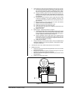
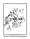
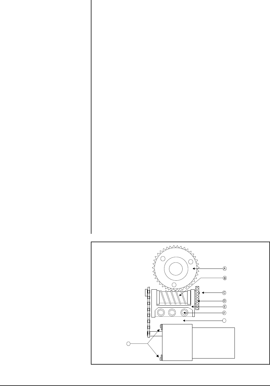
a. Verify that the worm drive (B) is fully seated in the worm gear (A). If it is not:
(1) Locate the worm-driven gear for either the pan or the tilt motor link-
age. Loosen the three hex screws (F) holding the worm in place,
but leave enough thread in place to hold the assembly on the mount.
(2) Using your thumbs, gently move the worm forward or pull the as-
sembly back from the worm gear to either tighten or loosen the gear
spacing to the worm gear. Move the base of the pan and tilt to check
the adjustment.
(3) If you get movement in the base, press a finger down in the middle
of the worm assembly. If you get no movement in the base, use
your thumb and forefinger to pull the worm assembly back until you
get movement.
(4) When the spacing is correct, tighten the hex screws. Start with the
middle screw to ensure proper spacing.
(5) Remove the screw (C) in the gear train nut (D).
(6) Tighten the gear train nut to remove any play.
(7) Line up the hole in the gear train nut with the nearest hole in the
gear train bracket (E).
(8) Replace the screw.
b. Refer to Figure 1. Adjust chain tension, if needed:
(1) Locate the pan or tilt motor on the assembly. Loosen the hex screws
(H) that hold the motor to its mounting bracket. Depending on which
motor assembly you are adjusting, there will be either three (pan) or
four (tilt). (Only two screws are shown in Figure 1.)
(2) Using a screwdriver, pry the motor down (at G) to tighten for the
correct chain tension. (You should not be able to freely move the
motor with your finger, nor should it be so tight that it will not move
at all as this usually leads to binding.)
(3) Tighten the hex screws.
c. Using a controller, you should now be able to move the PT480 without
looseness or binding. If you have any problems, contact Pelco’s Techni-
cal Support Department.
5. Lubricate the chains. Use a Teflon chain lubricant, such as TriFlon™.
6. Replace the covers.
a. Grasp one cover half in each hand and position the covers on each side
of the pan and tilt unit.
b. Bring the two cover halves together, aligning the two pins in one cover
half with the mating holes in the other cover half.
c. When the cover halves are together, press downward to force the covers
into their latches.
d. Replace the screws in the covers.
Figure 1. Pan and Tilt Adjustments
H
G


