


6 Pelco Manual C1925M (3/99)
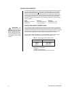
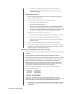
POWER REQUIREMENTS
An external power supply (not provided) is required when using CCC4000 Series cameras.
This camera will accept either AC or DC power in accordance with the chart immediately
below. A safety ground terminal ( ) is provided on the connector block to connect the
camera to ground potential. Maximum voltage between the supply inputs and the safety
ground must be less than 50 volts. Camera electronics are galvanically insulated from the
camera supply, which protects a system with more than one camera from ground loop
problems. The power connector block can be removed from the camera to ease mounting
and/or installation.
Model AC Power DC Power
CCC4000-2, CCC4001-2 12–27.6 VAC @ 60 Hz 10.8–39 VDC (2.7 W)
CCC4000-2X 12–24 VAC @ 50 Hz 10.8–34 VDC (2.7 W)
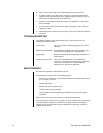
POWER AND VIDEO CONNECTIONS
If you are using AC power and are wiring more than one camera to the same transformer,
connect one side of the transformer to the same terminal on all cameras, and connect the
other side of the transformer to the remaining terminal on all cameras. Failure to connect all
of the cameras the same will cause the cameras to be out of phase with each other and
may produce what appears to be vertical roll when switching between cameras.
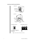
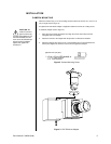
Connect a video cable to the SIGNAL OUT connector (BNC) on the rear of the camera
(refer to Figure 1). Refer to Table A for the type of video coaxial cable to use.
Table A. Video Coaxial Cable Requirements
Cable Type* Maximum Distance
RG59/U 750 ft (229m)
RG6/U 1,000 ft (305m)
RG11/U 1,500 ft (457m)
* Minimum cable requirements:
75 ohms
All-copper center conductor
All-copper braided shield with 95% braid coverage
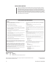
WARNING:
Be
sure to connect the
power and ground
leads to the appropriate ter-
minals. Wrong connections
may cause malfunction and/
or damage to the video
camera.