6 C1407M-H (1/07)
MATING CONNECTOR ASSEMBLY
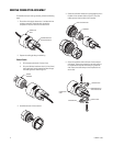
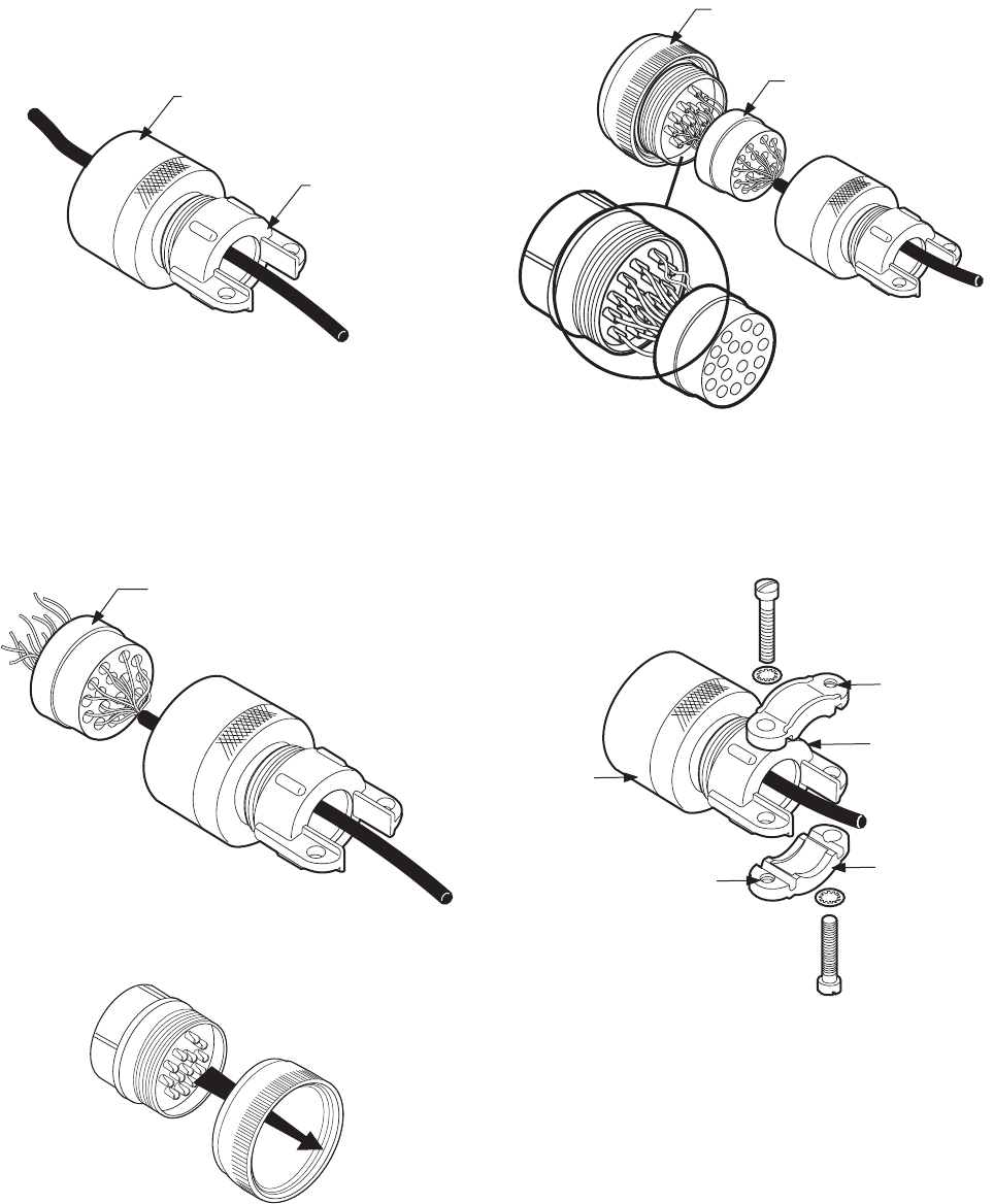
To assemble the 16-pin mating connector, perform the following
steps:
1. Discard the white plastic sleeve that is included with the
connector assembly. Thread the cable through the
compression nut/strain relief and connector shell.
2. Prepare the cabling by doing the following:
Control Cable
a. Strip the outer jacket back 2 inches (5 cm).
b. Strip the individual conductors back 1/4-inch (6 mm)
and thread them into the appropriate holes through
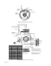
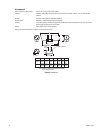
the rubber grommet. Refer to Figure 2.
3. Assemble the back of the connector.
4. Solder the individual conductors to the appropriate pins in
the back of the connector (refer to Figure 2). Push the
rubber grommet into the back of the connector.
5. Screw the connector shell to the back of the connector
and tighten. Tighten the compression nut/strain relief as
far as possible to compress the sealing ring inside the
shell. Attach the cable clamps to the compression nut/
strain relief.
CONNECTOR
SHELL
COMPRESSION NUT
AND STRAIN RELIEF
RUBBER
GROMMET
BACK OF CONNECTOR
GROMMET
THREADED END
COMPRESSION NUT
AND STRAIN RELIEF
CABLE CLAMP
THREADED END
CONNECTOR
SHELL


