


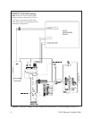
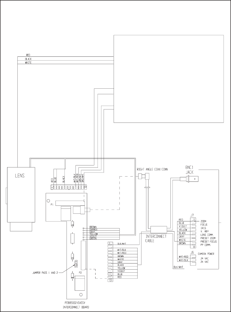
Figure 1. Schematic Diagram for Color Camera/Lens with Manual Iris Override (Model IOP08C3J-1)
This wiring diagram is for the
IOP08C3J-1 camera/lens package
only
. Please refer to this wiring diagram
during installation and operation, if neces-
sary. Figure 4 in manual C1441M-A pro-
vided with the unit is not applicable for this
camera/lens configuration.
2 PELCO Manual C1444M-A (5/96)
(3) OUTPUT AUTO IRIS 10V
(5) GROUND
(4) AUTO IRIS VIDEO SIGNAL
(7) VIDEO OUTPUT CORE
(2) VIDEO OUTPUT SHIELD
(8) 24 VAC IN
(7) 24 VAC IN
VIDEO
PROCESSING
BOARD
TO PCB8500150 BOARD
OF DOME DRIVE
TO P8,
PIN 7