


4 Pelco Manual C221M-C (6/03)
INSTALLATION
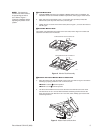
The following parts are supplied:
1 Mount arm
1 Rack base
2 Rack sides
11 1/2-inch NPT pipe
6 #8 x .50-inch, Phillips, pan head screws and finishing washers (use for PMC21A sides
and feet)
2 M4 x 12 mm, Phillips, pan head screws and washers (use for PMCS19A feet)
2 M6 x 12 mm, Phillips, pan head screws and washers (use for PMCS19A sides)
2 10-32 x .375-inch, Phillips, pan head screws and lock washers
2 5/16-18 x .75-inch hex bolts and lock washers
2 End caps for top and bottom of mount arm
1 .50-inch hole plug
1 3/16-inch Allen wrench
1 3/32-inch Allen wrench (for set screws)
14 cc tube of anti-seize
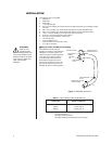
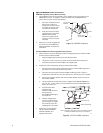
TOP SET SCREW
SWIVEL COLLAR
(FEEDTHROUGH)
BOTTOM SET
SCREW
FEEDTHROUGH
HOLE
FEEDTHROUGH
HOLE
TOP END
CAP
FEEDTHROUGH FOR
ICS-DO101ABK
01120
Table A. Video Coaxial Cable Requirements
Cable Type* Maximum Distance
RG59/U 750 ft (229 m)
RG6/U 1,000 ft (305 m)
RG11/U 1,500 ft (457 m)
*Minimum cable requirements:
75 ohms impedance
All-copper center conductor
All-copper braided shield with 95% braid coverage
ᕡ Prepare Video and Electrical Cabling
The MR5000L monitor mount is
capable of providing a concealed wire
installation. To conceal cables, pull
cables through the feedthrough holes
of the mount arm. Refer to Figure 1
for feedthrough hole locations. To
feed cables through the top of the
swivel collar, temporarily remove the
top end cap from the mount arm (if
installed) to assist in directing cables.
Figure 1. MR5000L Mount Arm
CAUTION:
Refer to local
electrical codes
before installing these units.
Local codes dictate how to
prepare wiring for all equip-
ment. Refer to Table A for
video coaxial cable
distances.