


Pelco Manual C342M-D (8/05) 11
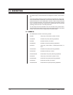
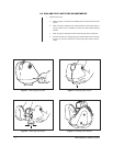
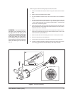
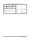
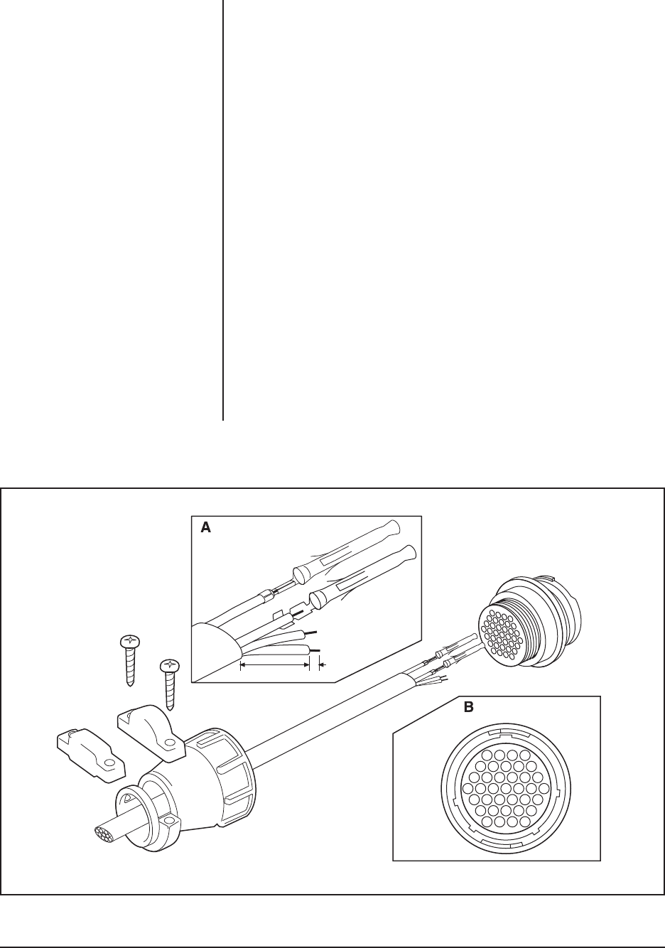
Refer to Figure 9 and the following steps to construct the cable:
1. Slide the unshielded and coaxial cables through the cable shell and rubber
boot.
2. Strip one inch of the jacket from the cables.
3. For the unshielded conductors, strip 1/8 inch of insulation from the individual
wires.
4. For the coax, unwrap the braid and twist it into a single conductor. Strip 1/8
inch of insulation from the center conductor. If you are using two coax cables
- one for video output and one for camera synchronization - twist the braid
from the two coax cables together.
5. Insert the end of each wire into a socket and crimp the end of the socket over
the wire’s insulation. This provides strain relief for the bare wire. Then crimp or
solder the bare wire to the socket.
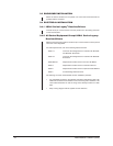
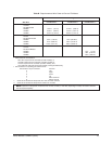
6. Refer to Table A and push each socket into the proper hole of the 37-pin con-
nector until it snaps into place. Once a socket snaps into place, it can not be
removed without a special AMP tool.
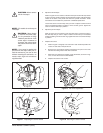
7. Slide the cable shell down the cabling and screw it to the 37-pin connector.
8. Screw the cable clamp to the cable shell.
9. Connect the 37-pin connector to the mating connector on the pan/tilt unit.
10. To make a watertight assembly, use RTV silicone on both sides of the connec-
tor to fill any gaps between the cable clamps, cable shell, and cable.
Figure 9. Connector Assembly
OR
00173
1"
1/8"
FRONT VIEW
14
59
15 10
22 16
28 23
33 29
37 34
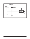
WARNING:
To prevent damage to
the wiper, if your enclosure has one,
AC high to turn on the wiper (pin 25
of the 37-pin connector) must come
from the same circuit that provides
power to the wiper (pin 15 of the 37-
pin connector). This is because the
wiper and the on/off control share the
same AC neutral (pin 16). See Fig-
ure 10.