


20 Pelco Manual C342M-D (8/05)
5.0 MAINTENANCE
If you need to remove the enclosure, protect the RediLINK™ connector area against
moisture, dust, dirt, etc. Failure to do so could result in a bad connection. Also,
damage to the pan/tilt unit or enclosure could occur when power is turned on.
The following servicing should be done every six months with average use.
1. Remove the PT780’s outer casing. (Refer to step 1 under Section 3.2, PAN
AND TILT STOP LIMIT ADJUSTMENTS.)
2. Inspect the gaskets around the cover, tilt shaft, and spindle for damage.
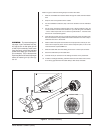
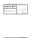
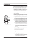
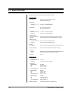
3. Refer to Figure 11. It shows the parts locations of the tilt assembly. Look for
similar orientations of parts when adjusting the pan assembly.
4. Check the backlash adjustment.
Backlash is the slack or binding in a pan and tilt base mount. Determine back-
lash by lifting the mount assembly, grasping the base, and wiggling it. There
should not be any play or binding between the gear (A) and worm drive (B).
Play or binding indicates a backlash problem.
• One backlash problem involves a worm and worm gear connection loose
enough to cause slipping or tight enough to cause binding.
• The second involves a too-loose or too-tight chain, usually causing symp-
toms similar to the worm and worm gear problem–slipping or binding.
a. Verify that the worm drive (B) is fully seated in the worm gear (A). If it is not:
(1) Locate the worm-driven gear for either the pan or the tilt motor link-
age. Loosen the three hex screws (F) holding the worm in place,
but leave enough thread in place to hold the assembly on the mount.
(2) Using your thumbs, gently move the worm forward or pull the as-
sembly back from the worm gear to either tighten or loosen the gear
spacing to the worm gear. Move the base of the pan and tilt to check
the adjustment.
(3) If you get movement in the base, press a finger down in the middle
of the worm assembly. If you get no movement in the base, use
your thumb and forefinger to pull the worm assembly back until you
get movement.
(4) When the spacing is correct, tighten the hex screws. Start with the
middle screw to ensure proper spacing.
(5) Remove the screw (C) in the gear train nut (D).
(6) Tighten the gear train nut to remove any play.
(7) Line up the hole in the gear train nut with the nearest hole in the
gear train bracket (E).
(8) Replace the screw.
b. Refer to Figure 11. Adjust chain tension, if needed:
(1) Locate the pan or tilt motor on the assembly. Loosen the hex screws
(G) that hold the motor to its mounting bracket. Depending on which
motor assembly you are adjusting, there will be either three (pan) or
four (tilt). (Only two screws are shown in Figure 11.)
Figure 11. Pan/Tilt Adjustments
H
G