


Pelco Manual C1423M-D (10/03) 13
6.0 CIRCUIT BOARD KIT INSTALLATION
This section provides instructions for installing the O/I-PCB circuit board kit.
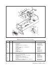
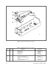
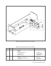
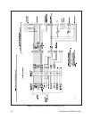
For the following instructions, refer to Figure 4. Table E lists the parts shown in
Figure 4.
1. Install the circuit board kit (O/I-PCB):
a. Remove the mounting bracket from the circuit board. It is not required.
b. Install two 4-40 x 1/4-inch screws, washers, and grounding clips (items
B, C, and D) in the circuit board. Bend the tabs of the grounding clips into
a “U” shape so that the ends touch the underside of the board.
c. Place the circuit board insulator (item 7) under the circuit board and mount
them to the enclosure with the two screws.
Save the wires with the plugs, and the plastic power supply barrier cover
(item 4). You will need them later.
You do not need the machine screws in the O/I-PCB kit. They are for
other installations.
2. If you installed a blower kit, connect the plug from the fan into the FAN socket
on the circuit board.
If you installed a heater kit, connect the plug from the heaters into the HTRS
socket on the circuit board.
If you installed a defroster kit, connect the plug from the defroster into the DEF
socket on the circuit board.
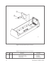
3. Reinstall the camera and sled.
4. Reconnect the video output from the camera.
5. If used, reconnect the camera’s synchronization cable.
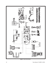
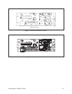
6. If your camera has a motorized zoom lens control, connect or wire the camera’s
lens control to the LENS or LENS CONTROL connector on the circuit board.
Refer to Figure 5 to see where to connect different lens connector options.
7. Wire the 10-connector INPUTs terminal on the circuit heard to the lens con-
troller as follows
• Lens Common - Connector 1
• Focus - Connector 2
• Zoom - Connector 3
• Iris - Connector 4
• Preset Common - Connector 5
• Preset Focus - Connector 6
• Preset Zoom - Connector 7
• Preset High - Connector 8