


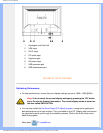

Product Information
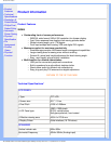
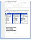
* This data is subject to change without notice.
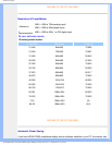
* Resolution 1680x1050, standard size, contrast max., brightness 50%, 6500° K, full white pattern.
RETURN TO TOP OF THE PAGE
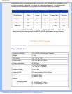
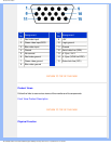
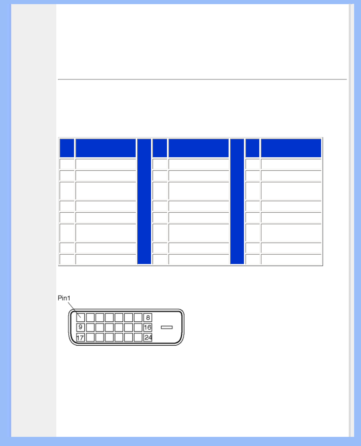
Pin Assignment
1. The digital only connector contains 24 signal contacts organized in three rows of eight contacts.
Signal pin assignments are listed in the following table:
Pin
No.
Signal
Assignment
Pin
No.
Signal
Assignment
Pin
No.
Signal
Assignment
1
T.M.D.S. Data2-
9
T.M.D.S. Data1- 17 T.M.D.S. Data0-
2
T.M.D.S. Data2+
10
T.M.D.S. Data1+ 18 T.M.D.S. Data0+
3
T.M.D.S. Data2/4
Shield
11
T.M.D.S. Data1/3
Shield
19
T.M.D.S. Data0/5
Shield
4
No connect
12
No connect 20 No connect
5
No connect
13
No connect 21 No connect
6
DDC Clock
14
+5V Power 22
T.M.D.S. Clock
Shield
7
DDC Data
15
Ground (for +5V) 23 T.M.D.S. Clock+
8
No connect 16 Hot Plug Detect 24 T.M.D.S. Clock-
2. The 15-pin D-sub connector (male) of the signal cable:
file:///D|/My%20Documents/dfu/200W6/english/200W6/product/product.htm (5 of 7)2005-06-28 1:43:39 PM