


13
13
English
12
8
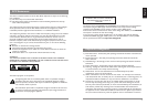
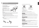
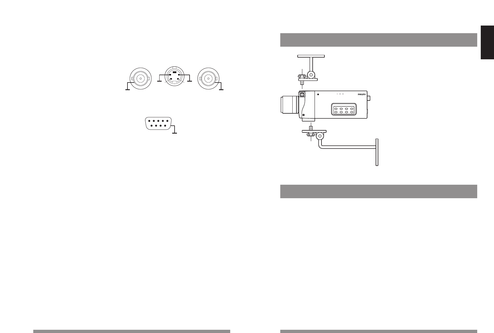
Mounting the camera
Top mounting: 1/4” 20 UNC
Max lens weight: 0.5 kg
Bottom mounting: 1/4” 20 UNC
Max. lens weight: 1.5 kg
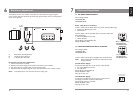
9.1 HOW TO SET UP YOUR CAMERA
The camera has 8 buttons which can be operated from the side of the camera.Feedback is
provided by means of On Screen Display. Extended setup functions are possible via the
software configuration tool.
Mode = Mode selection
LVL = Video Level
BLC = Back Light Compensation
AWB = Auto White Balance
LL = Linelock
Phase = Linelock-phase, H-phase or Vext phase
+ = Increase or On
- = Decrease or Off
After pressing a function button,the – or + buttons operate on the selected function:
– : Decrease or Off
+ : Increase or On
These functions automatically increase when the button is depressed for a longer period.
For all functions the - and + actions are positive choices.There are no toggle functions and
no cycles.
Digital Colour Camera
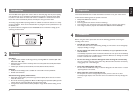
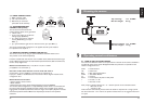
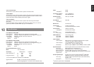
7.3 VIDEO CONNECTIONS
ᕃ BNC composite video
ᕄ Y/C 4 pin connector or
ᕄ Balanced 4 pin connector
(selectable via PC software)
7.4 SYNCHRONIZATION
CONNECTION (SYNC)
The vertical and horizontal camera
synchronization signals can be generated:
• internal x-tal;
• by the mains supply or the AC low
voltage supply (50/60 Hz);
• by a video signal from an external
source (PAL/NTSC), sync input
BNC ᕅ;
• by a synchronization signal from an external source, sync input BNC ᕅ.
The camera automatically configures for the applied external synchronisation.
For adjustment see chapter 9.
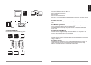
7.5 REMOTE CONTROL CONNECTION (RS-232)
The camera can be set up using an optional Windows based PC software tool.
This product can be ordered separately.
Functions available with this software tool are:AGC manual,Automatic. Electronic Light
Control (ELC).Dynamic Contrast. Gamma/Compression/Contour, OSD remainder text,
Camera set-up logbook etc.
RS-232 communication: Pin 3 = Rx, Pin 2 = Tx, Pin 5 = GND
pin 4,6,8,9 are not connected ᕆ.
Hard wire mode switch between current mode and mode 3
Connect Pin 1 to pin 5 (GND) by a switch.(refer to chapter 9.2.1)
Input pin 1: 10kΩ to +5V. Default active Low. Selection Active High or Disable via PC
configuration tool.
RS-232 Connector functions
• Camera system remote control.
• Mode selection
• Advanced Camera set-up via PC based Configuration tool LTC 0650/00.
The windows based configuration is a separate Philips product which is not included with
the camera itself.Functions available with this software tool are: Mode set-up and PC
logging.AGC manual, Boost,Automatic. Electronic Light control (ELC). Dynamic Contrast.
Gamma/Compression/Contour/Black level.Input/output functions and impedance
selections.
9
Operating controls and features
1
12345
6789
2
3
+
4
–
ᕅ ᕄ ᕃ
H-V LOCK Y/C OUT/ Balanced CVBS OUT
Sync. Input Video output Video output
Ground
N. C.
Rx
Tx
Mode
switch
N. C.
N. C.
N. C.
N. C.
ᕆ
RS232 4