


2.2 Physical Details
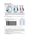
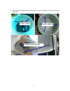
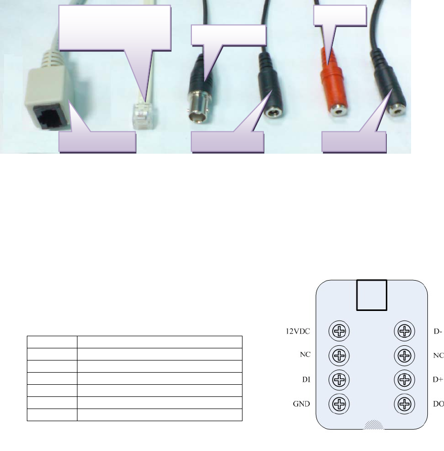
Identification of ICA-601 / ICA-651 cables
RS-485 & DI/DO
(Connect to the
bundled TEL box
)
RJ-45 LAN
Line In
Video Out
Line Out 12V DC In
1. RJ45 LAN socket: Connect to PC or Hub/Switch. For connect to 10Base-T Ethernet or
100Base-TX Fast Ethernet cabling. This Ethernet port built N-Way protocol can detect or
negotiate the transmission speed of the network automatically. Please use Category 5
“straight through” cable to connect the ICA-601 / ICA-651 to a 100Mbps Fast Ethernet network
switch or hub.
NOTE: In case you need to connect the device to PC or notebook directly, you should use
cross over cable instead.
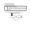
2. RS-485 & DI/DO: Connect RS-485 to external scanner and
connect to sensor in and alarm out devices.
Inside the TEL box:
Name Function
12VDC DC 12V output (50mA maximum)
GND GND
D+ RS485 data +
D- RS485 data -
DI Digital signal input
DO Digital signal output
NOTE: The RS-485 of ICA-601 / ICA-651 is master that can control external scanner.
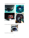
3. Local Video output (BNC port): The Network Camera also provides composite video output.
User can use BNC video cable to connect the Network Camera with a TV monitor or VCR.
4. DC-in Jack: The input power is 12VDC. Note that supply the power to the Network Camera
with standard power adapter included in package. Otherwise, the improper power adapter
may damage the unit and result in danger.
5. Line in (audio in): Connect an audio input source to the ICA-601 / ICA-651.
6. Line out (audio out): Connect a loud speaker to the ICA-601 / ICA-651. This function is for
voice alerting and two-way audio.
9