


Section 4 - Camera Hardware
Page 24
required is that with most modern telescope mounts the drift over the relatively short 1 minute
interval is small enough to preserve round star images, a feat that even the best telescope
mounts will not maintain over the longer ten minute interval. The Track and Accumulate
software does allow correction of the telescope position in the interval between snapshots to
keep the guide star grossly positioned within the field of view, but it is the precise co-
registration of images that accounts for the streakless images.
The host software and the CCD camera control the telescope through the 9-pin
Telescope port on the camera. This port provides active low open collector signals to the
outside world. By interfacing the camera to the telescope's controller the CPU is able to move
the telescope as you would: by effectively closing one of the four switches that slews the
telescope.
Note: You only need to interface the camera's Telescope port to your telescope if you are
planning on using the camera system as an autoguider or selfguider, or feel you need to
have the Track and Accumulate command make telescope corrections between images
because your drive has a large amount of long term drift.
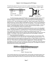
Some recent model telescopes (like the Celestron Ultima and the Meade LX200) have
connectors on the drive controller that interface directly to the camera's TTL level Telescope
port. All that's required is a simple cable to attach the 9 pin Telescope port to the telescope's
telephone jack type CCD connector. SBIG includes its TIC-78 (Tracking Interface Cable
Adapter) for this express purpose although it is easy to modify a standard 6-pin telephone
cable for interface to the Telescope port (see Appendix A for specific pin outs, etc.). The TIC-78
plugs into the 9-pin port on the ST-7E/8E/9E, and a standard phone cable, which we supply,
connects the adapter to the telescope drive. Note: phone cables come in a few variations. We
use the six-pin cable, and the pin order is reversed left to right relative to the connector from
one end to the other. This is identical to what is typically sold at Radio Shack stores as an
extension cable.
4.4.1 Using Mechanical Relays
Older telescopes generally require modifying the hand controller to accept input from the
camera's Telescope port. The difficulty of this task varies with the drive corrector model and
may require adding external relays if your drive corrector will not accept TTL level signals. We
maintain a database of instructions for the more popular telescopes that we will gladly share
with you. For a minimal charge will also modify your hand controllers if you feel you do not
have the skills necessary to accomplish such a task. We sell a mechanical relay box that
interfaces to the ST-7E/8E/9E, and will interface to the older drives. Contact SBIG for more
information.
In general, the camera has four signals that are used in tracking applications. There is
one output line for each of the four correction directions on the hand controller (North, South,
East and West). Our previous cameras had internal relays for the telescope interface, but with
the proliferation of TTL input telescopes the relays were removed in the ST-7 and ST-8 (we do
offer an external relay adapter accessory). The following paragraphs describe the general-
purpose interface to the telescope which involves using external relays.
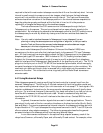
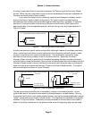
In our older camera models and in the optional relay adapter accessory, each of the
relays has a Common, a Normally Open, and a Normally Closed contact. For example, when