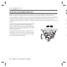
10 – DIGITAL COLOR DOME CAMERA
Introduction
•
❖
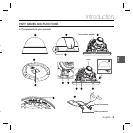
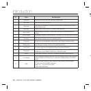
No Name Brief description
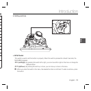
1 Cover dome Covers the inner cover, lens, and main body to protect them.
2 Inner cover Covers the main body to protect it.
3 Wing locker
Push a long thin screwdriver into its narrow spot and press it outward when you want to
remove the inner cover.
4 Main body Includes a lens, a switch board, a PCB board, screws, and such.
5 Mount bracket
Used as a ceiling or wall fi xture. It is fi xed using three long tab screws provided in the
package.
6 Wiring Passage
This passage is designed to make arrangement of the cables if you drill a hole to extend the wiring.
7 Zoom lever Using this lever, the lens zoom can be adjusted and fi xed.
8 Focus lever The lens focus can be adjusted by rotating it left or right. Rotate it clockwise for fi xing.
9 Tilt fi xing screw Using this screw, the slope of the lens can be adjusted and fi xed.
10 5-way Switch This switch is used to set and adjust the settings of the camera’s functions.
11 Groove mark
To attach the Main body to the Mount bracket, align this groove mark on the Main body with
the wide groove in the CAMERA FRONT side on the Mount bracket.
12 Locker Used to open or close the Cover dome. To open the cover dome, press the locker.
13 Lock releaser
Push it outward and rotate the main body in UNLOCK direction when you want to remove
the Mount bracket from the Main body or to remove the installed camera from the Mount
bracket.
14 Cable
Connect the Video connector to BNC cable and Power connector to power adapter.
EXT. D/N is a port for DAY/NIGHT conversion.
High(DC +3V ~ +5V): DAY(COLOR) Mode.
Low(0V): NIGHT (BW) Mode.


