SPEED DOME CAMERA User’s Manual
14
SPEED DOME CAMERA User’s Manual
15
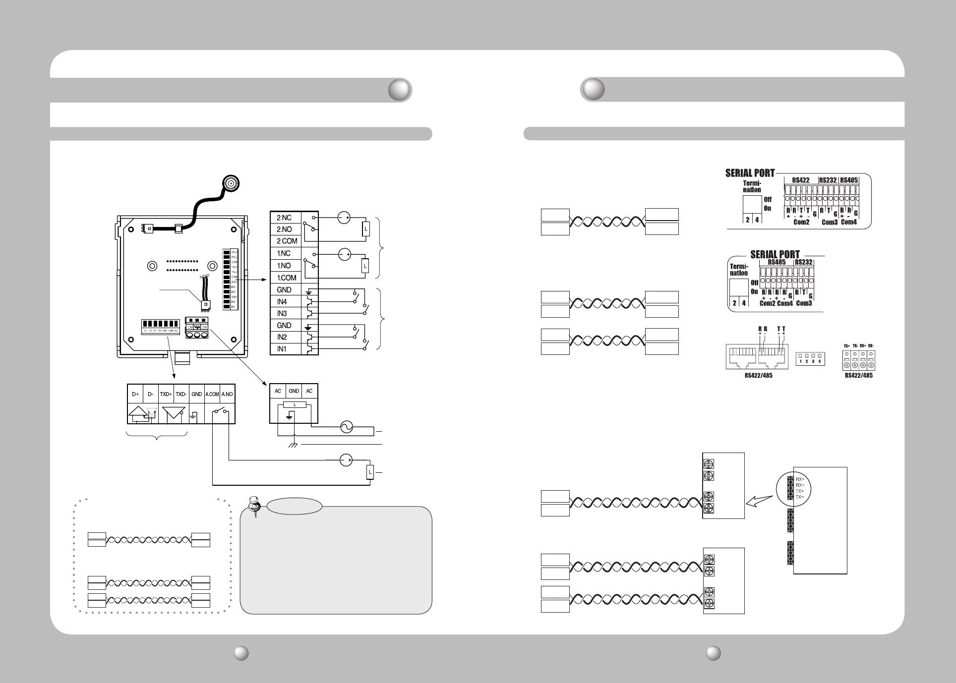
Communications and AUX
Refer to the below Control
Signal Connection chart
Power Supply
AC24V 2.5A
Power Input
Ground
AUX Output
For the camera wiring, please refer to the picture below.
The camera’s wiring interface board is equipped to a housing that is sold separately.
Connecting with Samsung Techwin’s “Stand Alone DVR”
Connecting with the Samsung Techwin Controller SCC-3100A
Video Output
Alarm
Fan Heater
Connector
Alarm Output
Alarm Input
•Themaximumpowercapacityofthebuilt-in
relay is 30VDC/2A, 125VAC/0.5A, and
250VAC/0.25A.
•ConnectingthepowerconnectorandGND
incorrectly to the NC/NO and COM ports may
cause a short circuit and fire, damaging the
camera.
Notes
Component Names and Functions
Camera Wiring Interface Board (Sold Separately)
· RS485 Communications
· RS422 Communications
Camera
Camera
D+
D-
D+
D-
TXD+
TXD-
TXD+
TXD-
TXD+
TXD-
RXD+
RXD-
Controller
or DVR
Controller
or DVR
Control Signal Connection
· RS-485 :
· RS-422 :
Camera
Camera
D+
D-
TX+
TX-
D+
D-
RX+
RX-
RX+
RX-
TX+
TX-
TX+
TX-
SCC-3100A
Data Box PORT1
SCC-3100A
Data Box PORT1
SCC-3100A Data Box
· RS-485 :
· RS-422 :
Camera
Camera
D+
D-
D+
D-
TXD+
TXD-
T(TX)+
T(TX)-
T(TX)+
T(TX)-
R(RX)+
R(TX)-
Stand Alone DVR
Stand Alone DVR
SVR-1680/1660/1645/960/
SVR-945
SVR-1650/1640A/950E
SVR-940/450
Speed Dome Camara and Appliances Wiring Diagram
Installing Your Camera


