


COLOR CCD CAMERA User Guide
10
COLOR CCD CAMERA User Guide
11
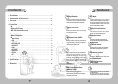
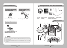
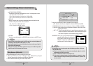
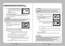
❶
Pan Base
:
control panning angle of camera
2
Rotate Base
:
control rotating angle of camera
3
X3.6 Vari-focal Lens Module
4
Rotate Base Holding Screw
:
fix rotated position
5
Pan Base Holding Screws (Color : Silver)
:
fix panned position
6
RS-485 Control Cable
:
The detailed description refers to p12
7
Power Input Jack
8
Video Output Jack
9
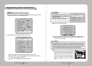
Function Setup switch
:
display the menu on the screen and move the cursor to four
directions to confirm status or after changing a selected item.
❿
Video Output Terminal to Monitor
⓫
Dome Cover
⓬
Shield Case
Overview
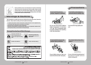
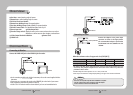
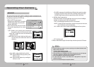
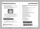
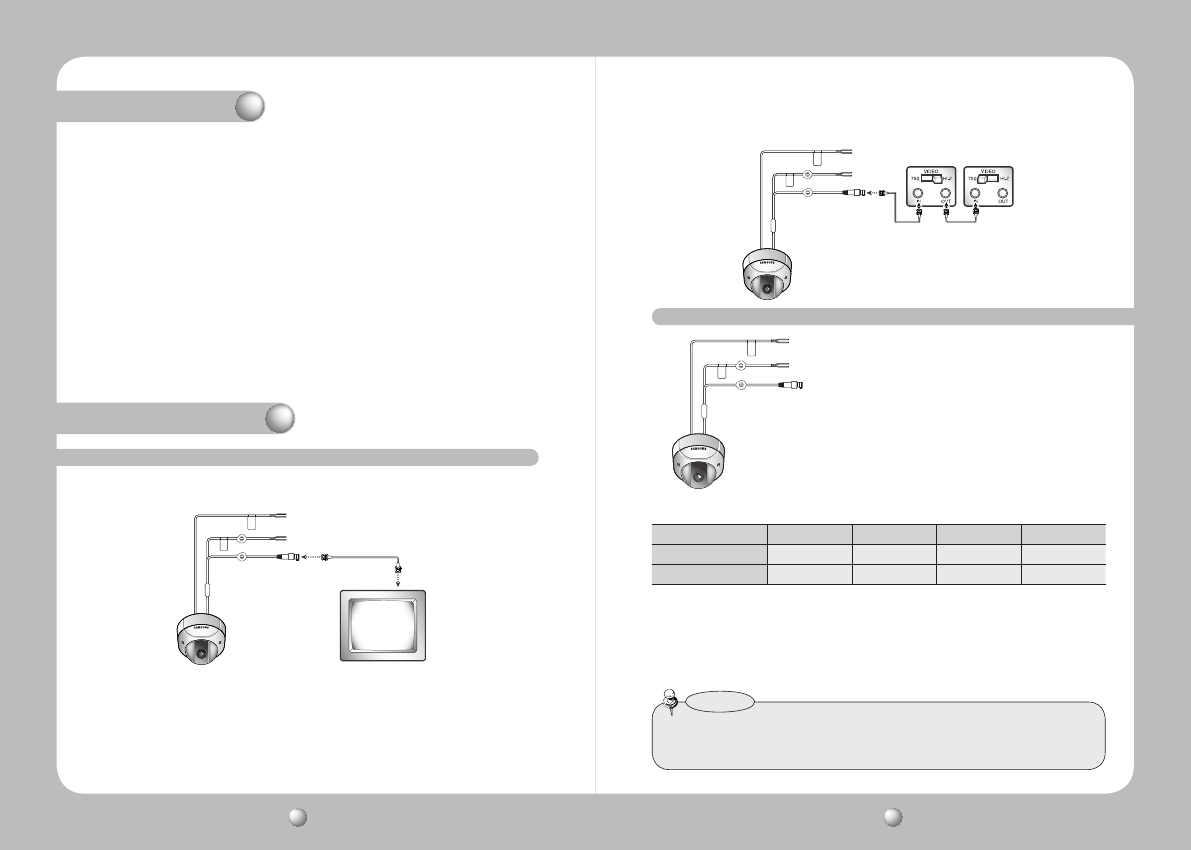
Connect the VIDEO-OUT jack to the VIDEO-IN jack of monitor.
Connection
Monitor
CCTVCamera
CCTVCamera
Intermediate Endmonitor
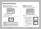
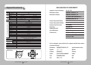
Connect the adaptor to the power input
connector as shown in the figure below.
The recommended adaptor specification
for SVD-4600 is AC 24V / 500mA or DC 12V
/ 500mA.
power input terminal
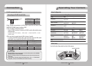
• As shown in the table above, voltage decreases as the wire gets longer. Therefore use of an
excessively long adaptor output line for connection to the camera may affect the
performance of the camera.
*Standard voltage for camera operation : DC 12V ± 10%, AC 24V±10%
*There may be some deviation in voltage drop depending on the type of wire and the manufacturer.
•Besuretoconnectpoweronlyafteralltheinstallationiscomplete.
•UsetheULlisted,class2powertransformerofAC24Vadaptor.
•GroundshouldbeconnectedtotheGNDterminal.
Notes
When the resistance value of copper wire is at [20ºC(68°F)]
Copper wire size (AWG) #24(0.22㎟) #22(0.33㎟) #20(0.52㎟) #18(0.83㎟)
Resistance (Ω / m) 0.078 0.050 0.030 0.018
Voltage Drop (V/m) 0.078 0.018 0.011 0.006
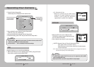
Connecting to Monitor
Connecting to Power
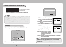
• As the connecting method varies with the instruments, refer to the manual supplied with the
instrument.
• If necessary, you can connect the monitor to the REMOTE jack on the back of your camera.
• Only connect the cable when the power is turned off.
• Set the 75Ω / Hi-Z selection switch as shown below if you have an intermediate device.