


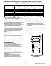
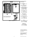
Electrical Specifications
HIP-205BE11, -205BE11-BO2, -200BE11, -200BE11-BO2, -195BE11,
-195BE11-BO2, -190BE11, -190BE11-BO2, -186BE11, -186BE11-BO2,
-180BE11, -180BE11-BO2 )
Model
HIP
- 205BE11,
- 205BE11- BO2
HIP
- 200BE11,
- 200BE11- BO2
HIP
- 195BE11,
- 195BE11- BO2
HIP
- 190BE11,
- 190BE11- BO2
HIP
- 186BE11,
- 186BE11- BO2
HIP
- 180BE11,
- 180BE11- BO3
Cell Number in Series [Pieces] 96 96 96 96 96 96
Maximum Power (Pmax) [W] 205 200 195 190 186 180
Maximum Power Voltage (Vmp) [V] 56.7 55.8 55.3 54.8 54.4 54.0
Maximum Power Current (Imp) [A] 3.62 3.59 3.53 3.47 3.42 3.33
Open Circuit Voltage (Voc) [V] 68.8 68.7 68.1 67.5 67.0 66.4
Short Circuit Current (Isc) [A] 3.84 3.83 3.79 3.75 3.71 3.65
Cell Type
Maximum System Voltage [V] 1000 1000 1000 1000 1000 1000
Factory Installed Bypass Diode Yes Yes Yes Yes Yes Yes
Weight [kg] 14 14 14 14 14 14
HIT* (hybrid of a- Si and mono c- Si)
Electrical Specification
*HIT= Hetero junction with Intrinsic Thin-layer
Note: The values in the above table are nominal.
4
Printed in Europe 20.10.2006
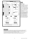
Module wiring
> The maximum number of HIP- xxxNHE5, xxxNHE5-BO2
modules that can be wired in series is seventeen (17).
> The maximum number of HIP-
BE11, xxxBE11-BO2
modules that can be wired in series is thirteen (13).
> When your PV system includes other components
(batteries, charge controllers, inverters, etc.), be sure to
follow the safety recommendations of their manufactures.
> These modules contain factory installed bypass diodes.
If these modules are incorrectly connected to each other,
the bypass diodes or cable or junction box may be
damaged.
Array Wiring
The term “array” is used to describe the assembly of
several modules on a support structure with associated
wiring.
Use copper wire that is sunlight resistant and is insulated
to withstand the maximum possible system open circuit
voltage. Check your local codes for requirements.
Electrical Protection
The HIP- xxxNHE5, -xxxNHE5-BO2,
--xxxBE11, -xxxBE11-BO2 Module complies with the
requirements of Electrical protection Class II.
If necessary, the module or array can be grounded.
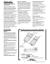
Module Terminations
A junction box as terminal enclosure is equipped for
electrical connections on SANYO modules.
The HIP- xxxNHE5, -xxxNHE5-BO2, -xxxBE11, -
xxxBE11-BO2 modules are equipped with MC plugs as
terminal enclosure.
Use these MC plugs for electrical connections.
Please contact your local dealer with questions
regarding other electrical connections for modules.
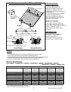
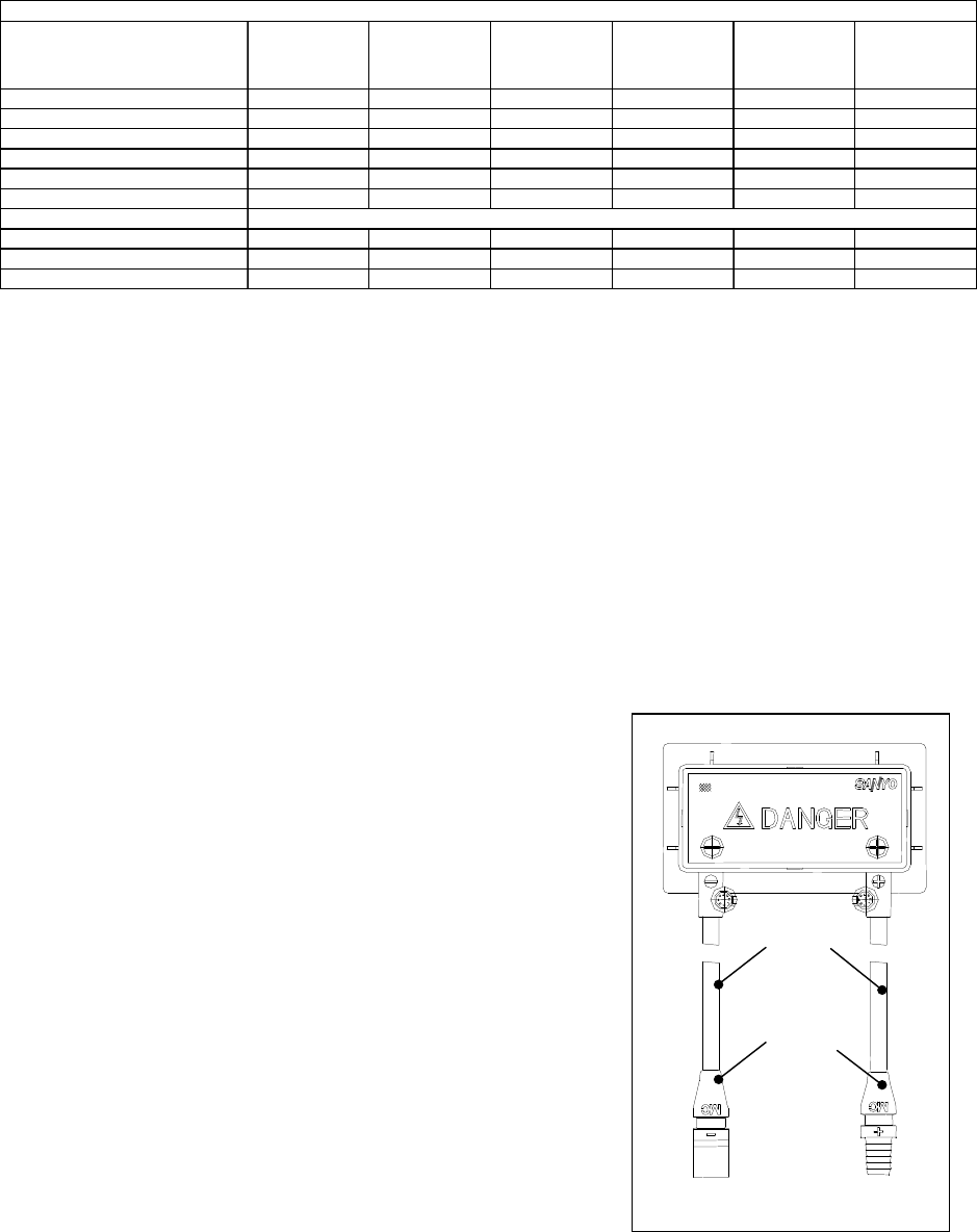
negative ( - )
positive ( + )
Figure3: Configuration of
junction box
Connector
(MC Plug)
Cable
Junction box configuration and
description of terminals (for reference)
Modules equipped with one junction box contain
terminals for both positive and negative polarity, and
bypass diodes.
Two terminals are dedicated to each polarity (with the
polarity symbols engraved onto the body of the junction
box ) (see Fig3).