


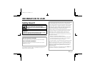
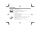
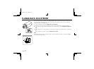
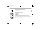
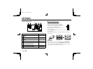

PARTS NAMES
1 Power indicator (POWER)
Comes on when the power to the camera is on.
2 Video output connector (VIDEO OUT: BNC type)
Connect this connector to a device such as a VCR or monitor with a VIDEO IN connector.
3 Manual color/black and white setting terminal (CONTROL)
• G (ground) terminal
• C (color) terminal
• B (black and white) terminal
4 Line phase adjustment volume (LINE PHASE)
When using two cameras or more, the image on the monitor may roll vertically when switching sources. This
rolling can be minimized by turning this volume.
5 24 V AC input terminal (24 V AC, GND)
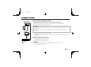
6 Camera setup section (under the cover)
These settings are for when using a 1/3 inch CS mount DC (without EE internal amplifier) type lens. However,
if due to installation conditions or environment the settings may need to be modified for best results (see
"SETTINGS").
To access the controls, loosen the cover fixing screw A, then remove the cover.
7 Lens iris output connector (LENS)
This 4-pin connector is used to send the DC control signal and power supply to an auto-iris type lens.
1
4
5
2
GCB
3
6
7
A
L53U4/US GB 1999, 10, 14
4 English