


POWER
CONTROL
LINE
PHASE
VIDEO
OUT
AC24V
C B G
FrançaisEspañol English
LINE PHASE
dial
POWER lamp
GND
DC12V
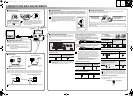
b Supported coaxial cables
Cable type – Length: RG-59U (3C-2V) – 250 m max.,
RG-6U (5C-2V) – 500 m max., RG-11U (7C-2V) – 600 m max.
• When using an RG-59U (3C-2V) cable, do not use it
on piping or air wiring.
• If you use a cable other than the type above, the
image or sync signal will be attenuated and will not be
transmitted correctly.
b Attaching the lens
Use any DC type and CS mounting lens equipped with an auto iris (sold separately).
3
22
1
Brake coil (–)
Brake coil (+)
Drive coil (+)
Drive coil (–)
5 mm max.
Pin layout for LENS terminal
• Depending on the type of the lens, the shape of
the lens plug may differ. In this case, consult your
dealer or an Authorized Sanyo Service Center.
• Apply adapter ring (sold separately) when you use
any C mounting lens.
b Camera attachment
When attaching the camera, make sure to verify that the attachment surface will allow full
tightening of the screws. Plaster board, etc., may not give a strong enough attachment, and
it is recommended to use a reinforcement, or other method so that the screws are anchored
securely.
b Flange-back adjustment
This normally does not need adjustment. If the picture is out of focus at the telephoto position,
adjust the flange-back position as described below.
When monitoring lighting or other extremely bright objects (which
exceed the maximum required illumination), smearing may occur in
the vertical or horizontal direction (either above and below the
high-brightness object or as a perpendicular band). In such a case,
adjust the angle of illumination and other factors while observing
the monitor.
Make sure to use the
screws to secure the
bracket.
Changing the
bracket topside out
Repeat steps 2 and 3 until the image stays in-focus when changing from a wide-angle position to
a telephoto position.
1
4
2
3
Set to the maximum
wide-angle position
and focus the picture.
Set to the maximum
telephoto position and
focus the picture.
Loosen.
Tighten.
b Power cable
b When a hunting reaction occurs
Under near infrared lighting or other similar conditions, hunting reaction may occur because the
Day/Night function is not carried out normally. In such case, refer to the following diagram for cable
connection to fix the image either to color or black-and-white by using an external switch, etc.
<AC 24 V connection>
<DC 12 V connection>
To prevent a fire hazard use any
UL listed wire rated VW-1.
Check that polarity is correct.
Fixing the image to color Fixing the image to back-and-white
You cannot control the switchover operation by using an external switch, etc., while switching between
color and black-and-white images is actually in progress by the Day/Night function.
GND AC24V
DC12V
CBG
CONTROL
CBG
CONTROL
AWG24: 600 m max.
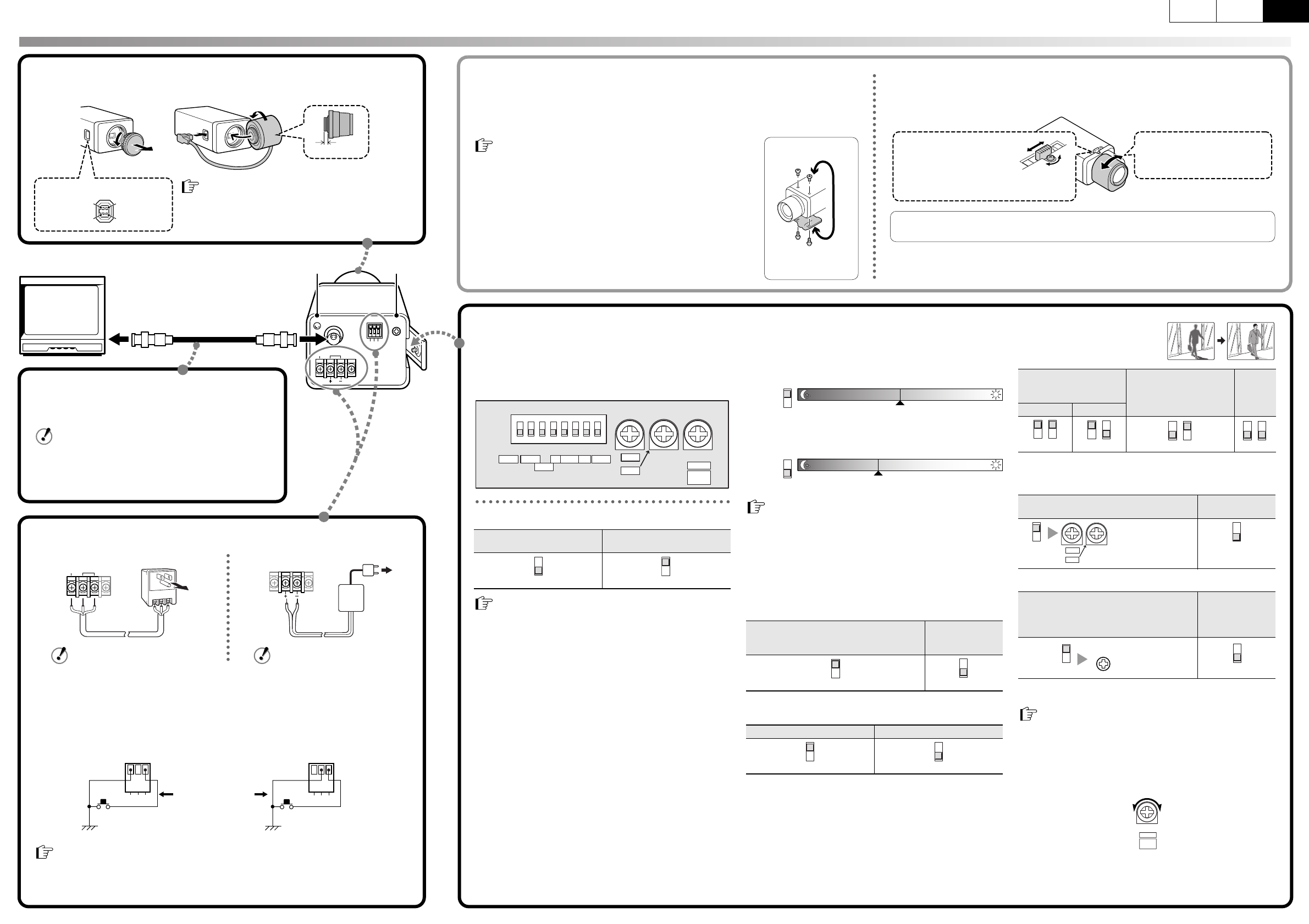
b Camera adjustments/settings
The camera comes pre-adjusted and ready to install at the time of
factory shipment, but you can make adjustments or settings if you
need.
If you have trouble adjusting the camera, consult your dealer or an
Authorized Sanyo Service Center.
<ES/EI> Iris setting
<C-BW> Day/Night function switchover point
This switch is used to set the timing for automatic switching
between color and black-and-white images.
a Set the switchover point to brighter side so that the automatic
switch may trip in brighter condition for switchover between color
and black-and-white images.
a Set the switchover point to darker side so that the automatic switch
may trip in darker condition for switchover between color and
black-and-white images.
<GAIN> Auto gain control (AGC)
* This setting causes noise generation and a grainy image.
<AP> Aperture compensation
<BLC> Backlight
compensation
Only when using an auto-iris lens
* If the background of the object is extremely dark, set to Center zone
metering.
<WB> White balance (color compensation)
<SYNC> Sync setting
* Adjust the roll by turning the LINE PHASE dial on the second and
subsequent cameras.
<LEVEL> Lens iris level adjustment
When using an auto-iris lens, if the entire image is too dark or too
bright, adjust the contrast.
Use of an auto-iris lens
Use of a manual or fixed
iris lens (for indoor use)
• Set the lens aperture to the shortest F-stop.
• When using a manual or fixed iris lens under fluorescent light, the
image may flicker.
• When using an auto-iris lens, if the entire image is too dark or too
bright, adjust the contrast by using the LEVEL dial.
87654321
MSB
HH MCSMWBLL
LSB L N N OFF ATW INT
ES/EI
ON
C-BW SYNC
RED
BLUE
GAIN
BLCAP WB
LH
A. I.
LENS
LEVEL
1
1
• The color image will be displayed first when the power is turned on.
• When switching between color and black-and-white images
automatically, it is normal for movement of the optical filter to be
heard and for a vertical black band to move across the screen.
• Switching from black-and-white to color may occur if there is a
significant degree of reflection from the object when using infrared
illumination in black-and-white image. Adjust the illumination to
avoid switching to color image.
• The focus setting position may differ between color and
black-and-white images. Carry out adjustment to ensure that the
focus for both images is in the optimum position.
High sensitivity
Increased electronic sensitivity to obtain a
bright image in a lower illuminance*
Normal
sensitivity
Sharp outline Normal outline
B/W ColorB/W Color
High
Switchover point
2
B/W ColorB/W Color
Switchover point
2
Low
3
3
4
4
Multi-spot metering
Backlight compensation
to the entire screen*
Center zone metering
Backlight compensation
to the central portion of
the screen
OFF
High Normal
Manual White Balance
Auto-Tracing
White balance
Line-Lock
(Only when using an AC power supply)
Synchronizes the unit with power
frequency*
Internal sync
If the vertical roll cannot be corrected by adjusting the LINE PHASE
dial on the second and subsequent cameras, try adjusting the LINE
PHASE dial on the first camera. If it still cannot be corrected, please
check that the polarity of the power cords of all connected devices is
correct.
Low (darker) High (brighter)
65
65
65
65
Turn clockwise to
augment the color.
RED
BLUE
7
7
(Rear panel)
LINE
PHASE
8
8
LH
A. I.
LENS
LEVEL
CONNECTIONS AND ADJUSTMENTS
L5BG2_US(VCC-4794)(ENGLISH).fm 2 ページ 2005年8月24日 水曜日 午前11時39分