


J
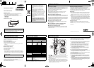
CHECKING THE CAMERA IMAGE
You can use the monitor checking cable (sold separately) to
display an image on a monitor when setting up the camera to check
the surveillance angle and range, lens focus, etc.
Connect the connector of the monitor checking cable to the monitor
checking connector (a) on the circuit board and connect the jack
of the monitor checking cable to the monitor.
J
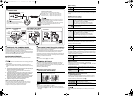
LENS ADJUSTMENTS
Once the camera has been installed, adjust the lens section.
Be careful not to touch the lens section when changing the angle
of the camera.
When loosening the drop-prevention cord fixing screw, be
careful not to loosen it too much; otherwise the dome cover may
drop.
1 Loosen the drop-prevention cord fixing screw, then adjust the pan
position (±180°) and the tilt position (±60°).
Loosen the screw (A) with a Phillips head screwdriver before
adjusting the tilt position.
2 Loosen the zoom lever screw, turn the zoom lever to the right/
left to determine the zoom position while viewing the camera
images on the monitor, and then re-tighten the screw.
3 Loosen the focus lever screw, turn the focus lever to the right/
left to determine the focus position while viewing the camera
images on the monitor, and then re-tighten the screw.
4 Tighten the drop-prevention cord fixing screw.
NOTE on image direction (Wall Installed):
If the monitor image is misaligned, follow the steps below to adjust.
cLoosen the screws (B) with the supplied hexagon wrench (small).
dTurn the indented dial (C) to adjust the image direction.
eTighten the screws (B) after adjustments are finished.
J
DAY/NIGHT FUNCTION (VDC-D1585VP)
When connected to power, the VDC-D1585VP turns on the DAY/
NIGHT function for continuous operation.
The DAY/NIGHT function automatically switches over between
color and black-and-white mode depending on the ambient
brightness; for example, choosing color mode during daytime, and
black-and-white mode for nighttime monitoring with its increased
sensitivity in a darker environment.
NOTE:
This function is disabled if 4 is set to "Down".
J
CAMERA SETTINGS
The camera comes from the factory pre-adjusted and ready to
install, but you can make adjustments or settings if you need.
If you have trouble adjusting the camera, consult your dealer or an
Authorized Sanyo Service Center.
(=Factory default setting)
1 Backlight compensation setting
(VDC-C1575VP, VDC-D1585VP)
NOTE:
This function is disabled if 4 is set to "Down".
If backlight compensation is not corrected in the VDC-C1575VP and
VDC-D1585VP when 1 is set to “ON”, you can correct by adjusting level
volume 6.
CONNECTIONS AND SETTINGS
ON
1234
1234
6
7
60 60
6
7
ON
1234
2354
J
CONNECTIONS
VDC-C1575VP / VDC-D1585VP
Check for polarity when using a DC 12 V
power supply (Polarity does not matter when
using a AC 24 V power supply).
Board on the
opposite side of the
lens
J
LENS ADJUSTMENTS
J
CAMERA SETTINGS
VDC-W1595VP
Black
Red
Supported coaxial cables
You can use any of the following coaxial cables:
RG-59U (3C-2V) Length: 250 m (273.4 yds) max.
RG-6U (5C-2V) Length: 500 m (546.8 yds) max.
RG-11U (7C-2V) Length: 600 m (656.2 yds) max.
When using an RG-59U (3C-2V) cable, do not attach it
to piping or wiring.
Select the cable according to the distance between the
devices you wish to connect.
If you use a cable other than the types above, the image
or sync signal will be attenuated and will not be
transmitted correctly.
Monitor checking
connector (a)
±180°(Pan)
Screw (A)
FOCUS
ZOOM
(Tilt)
Screw (B)
Monitor checking
connector (a)
DC 12 V/AC 24 V connection
Screw
(B)
Indented
dial (C)
Drop-
prevention
cord fixing
screw
ON
Compensates for backlighting with the
centerweighted metering mode.
Down
This function is off.
2 Iris setting
NOTE:
This factory preset is optimal, so it is not necessary to change the
setting.
3 White balance setting
VDC-C1575VP, VDC-D1585VP
VDC-W1595VP
4 Auto Gain Control (AGC) setting
For adjusting the sensitivity of the camera. Use this setting for
shooting in dark environments.
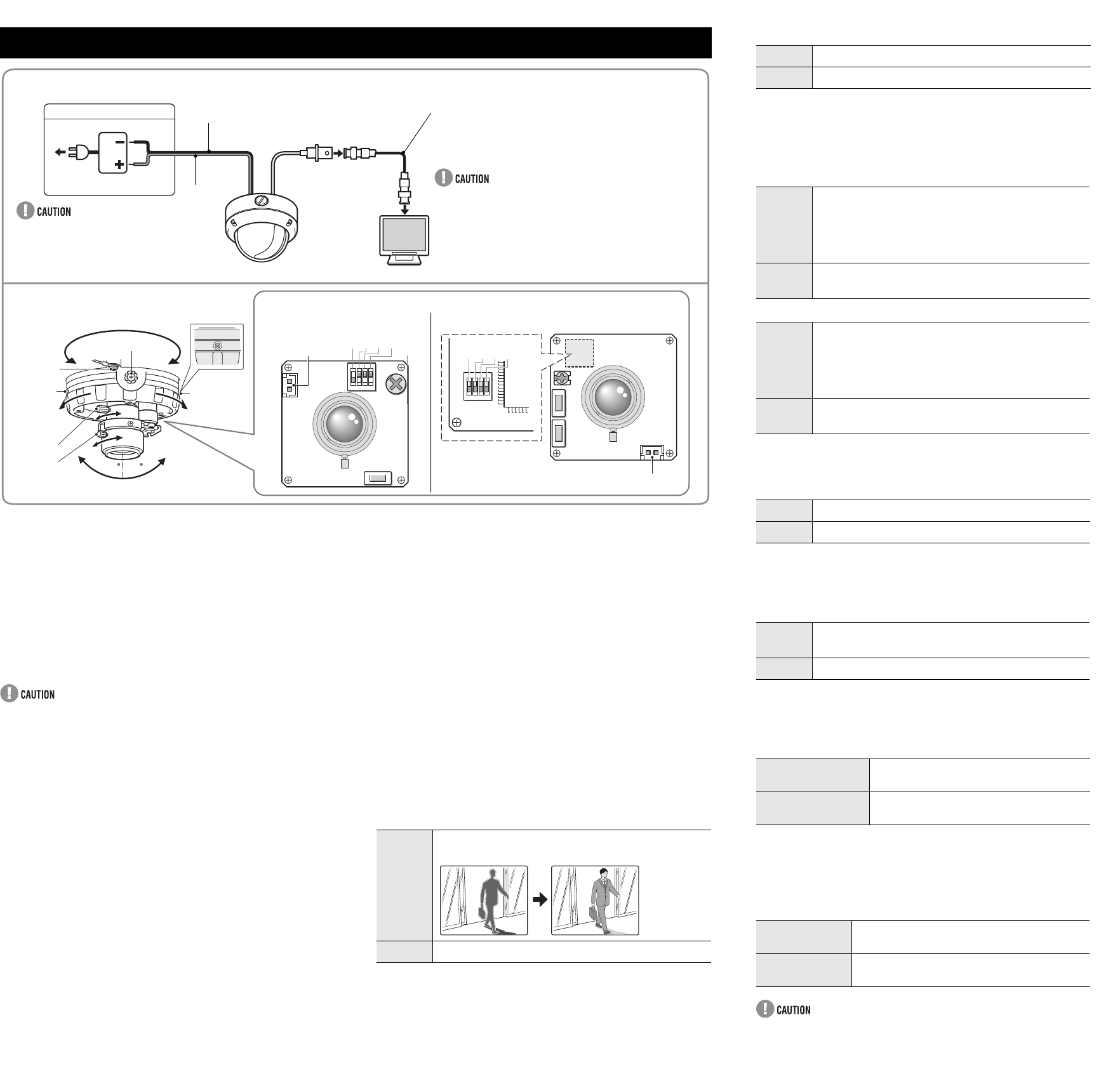
5 Wide dynamic range setting (VDC-W1595VP)
Correction is made for simultaneous monitoring of subjects which
are different in brightness, one in a dark room and another in bright
outdoor environment, for example.
6 Level volume
If the entire image is too dark or bright, or the backlight
compensation is not correct even after 1 is set to “ON”, you need
to adjust the level volume.
7 Adjusting synchronization error
(AC 24 V users only)
Vertical sync disturbance may occur when a selector is used to
switch between multiple cameras connected to one monitor. To
prevent vertical sync disturbance, adjust 7.
When using the DC 12V adaptor, sync setting is set to internal
sync.
ON
AI: Normal setting (Auto iris)
Down
EI: Electronic iris
ON
ATW-A (Auto-tracing white balance - All): Automatic
setting for white balance, covering wider range of
color temperature than with “
ATW
”.
•May result in an excessively and unnaturally
effected image, depending on the conditions.
Down
ATW (Auto-tracing white balance): Automatic setting
for white balance.
ON
Normal setting
Down
Set this when there is excessive noise (AGC off)
ON
When monitoring of subjects which differ in
brightness.
Down
This function is off.
Counterclockwise
(High)
Opens the lens iris, making the entire
image brighter
Clockwise
(Low)
Closes the lens iris, making the entire
image darker
VDC-C1575VP,
VDC-D1585VP
Press the button to eliminate sync
disturbances when needed.
VDC-W1595VP
Press each button to eliminate sync
disturbances when needed.
L5BN2_XE(VDC-C1575VP)(GB).fm 2 ページ 2006年12月1日 金曜日 午前12時12分