


– 10 –
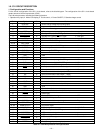
Pin
Signal
1
2~7
8
9
10
11
13
14~19
20
21
22
31
32~69
70
71
73
74
75
76
77
78
79
80
81
82
84
86
87
88~90
83
85
91~93
CHG VOL
SCAN IN
VREF
STBY (R) LED
STBY (G) LED
VSS
NOT USED
AVREF ON
BUZZER
CHG ON
NOT USED
VSS
NOT USED
P (A) ON
P ON
DIN CONNECT
CARD
AV JACK
SO
SCK
IC
XOUT
XIN
VDD
XCIN
XCOUT
RESET
BAT OFF
RXD
S. REQ
NOT USED
SCAN OUT0~2
I/O
I
I
I
I
O
-
O
-
O
O
O
-
-
-
O
O
I
I
I
I
O
O
-
O
I
-
I
O
I
I
I
I
-
O
Outline
Strobe charge voltage input (analog input)
Key matrix input
A/D converter standard voltage input terminal
Standby LED (red) ON/OFF signal L : LED light
Standby LED (green) ON/OFF signal L : LED light
GND
Self-timer LED ON/OFF signal L : LED light
-
A/D standard power ON/OFF signal L : ON
Buzzer output
Flash charge ON/OFF signal H : ON
-
GND
-
DC/DC converter (analog) ON/OFF signal H : ON
DC/DC converter (digital) ON/OFF signal H : ON
DIN jack connect detection signal H : Connection
Memory card attachment detection signal L : Attachment
AV output cable connection detection signal H : Connection
Serial communication data input (←ASIC)
Serial communication data output (→ASIC)
Serial communication clock output (→ASIC)
Connect to GND
Main clock oscillation terminal
Main clock oscillation terminal (4 MHz)
VDD
Sub clock oscillation terminal
Sub clock oscillation terminal (32.768 kHz)
Reset input
Battery OFF detection signal L : OFF
RS-232C RXD input terminal
Serial communication request signal L : Request
-
Key matrix output
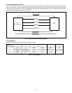
1-6. SY1 CIRCUIT DESCRIPTION
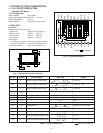
1. Configuration and Functions
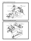
For the overall configuration of the SY1 circuit board, refer to the block diagram. The configuration of the SY1 circuit board
centers around a 8-bit microprocessor (IC301).
The 8-bit microprocessor handles the following functions.
1. Operation key input, 2. Mode LCD display, 3. Clock control, 4. Power ON/OFF, 5. Storobe charge control
SI
72
23~30
12
SELF LED
95
96
97
98
99
100
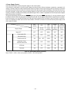
LCD ON
ASIC TEST 0
ASIC RESET
AVSS
BATTERY
O
O
O
O
-
I
LCD monitor power ON/OFF signal H : ON
ASIC reset signal L : Reset output
ASIC reset control signal L : Reset control
Analog GND
Battery voltage input (analog input)
ASIC reset control signal
ASIC TEST 2
94
WAKE UP
O
Wake up signal H : WAKE UP
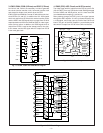
Table 4-1. 8-bit Microprocessor Port Specification
AVDD -
A/D converter analog power terminal